Advertisement
Quick Links
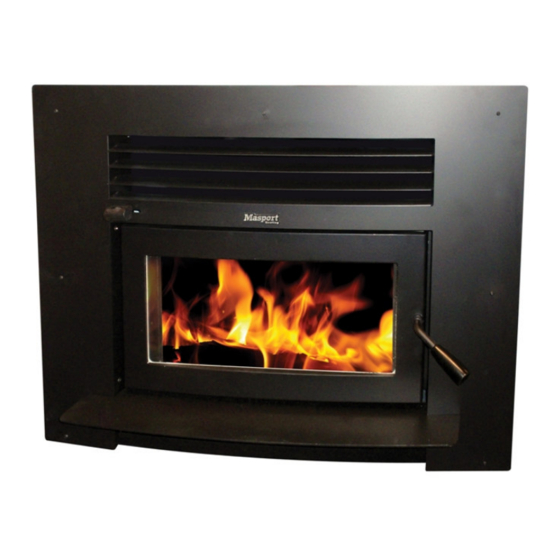
MASPORT I3000 DRY BUILT-IN FIRE
MASPORT I3000 WET BUILT-IN FIRE
INSTALLATION INSTRUCTIONS
Manufactured in New Zealand by:
GLEN DIMPLEX AUSTRALASIA LIMITED
P.O. Box 58473, Botany
MANUKAU 2163
Ph: 0800 666 2824
Fax: 09274 8472
Email: sales@glendimplex.co.nz
Web: www.glendimplex.co.nz
29.05.2012
Part. No. 593584
Distributed in Australia by:
GLEN DIMPLEX AUSTRALIA PTY LIMITED
Unit 1, 21 Lionel Road, Mount Waverley,
VICTORIA 3149
Ph: 1 300 556 816
Fax: 1 800 058 900
Email: sales@glendimplex.com.au
Web: www.glendimplex.com.au
1
Advertisement

Related Manuals for Masport I3000 DRY


Summary of Contents for Masport I3000 DRY
-
Page 1: Installation Instructions
MASPORT I3000 DRY BUILT-IN FIRE MASPORT I3000 WET BUILT-IN FIRE INSTALLATION INSTRUCTIONS Manufactured in New Zealand by: Distributed in Australia by: GLEN DIMPLEX AUSTRALASIA LIMITED GLEN DIMPLEX AUSTRALIA PTY LIMITED P.O. Box 58473, Botany Unit 1, 21 Lionel Road, Mount Waverley,... - Page 3 DIMENSIONS: Fig. 1 NOTE: The water booster can be installed with connections at right side or left side of fire. You need to check with your local council if you are allowed to have a water booster installed in that fire. INTRODUCTION In the interest of your safety, most building regulatory Authorities in Australia and New Zealand require any woodfire installation to comply with Installation Standard AS/NZS 2918:2001.
- Page 4 WE RECOMMEND THAT THE INSTALLATION OF YOUR MASPORT WOODFIRE BE CARRIED OUT BY A QUALIFIED SPECIALIST INSTALLER. IF ANY ELECTRICAL WORK IS REQUIRED, IT MUST IT MUST BE CARRIED OUT BY A LI- CENSED ELECTRICIAN. IN SOME REGIONS POWER POINTS ARE NOT PERMISSIBLE WITHIN THE FLOOR PROTEC- TOR AREA, PLEASE CHECK WITH YOUR LOCAL AUTHORITY.
-
Page 5: Installation Requirements
INSTALLATION REQUIREMENTS INSTALLATIONS- FLOOR TO CEILING ENCLOSURE: Inspect the house construction at the proposed installation position to verify that the flue cas- ing (250mm diameter, plus 12mm clearance all around) can pass right up through the ceiling space without requiring the removal of essential roof or ceiling support beams. The flue center- line will be 286mm from the rear wall and it must be at least 500mm distant from any side wall. - Page 6 It is usually convenient to carry the same material right up to the ceiling level. The side clad- ding of the enclosure may be GIB board or any other wall cladding material. You must leave the cladding off at least one side until the flue system has been installed. For heat sensitive floors, construct an ash floor protector of the shape shown in the Floor Plan above.
- Page 7 Slide the firebox cabinet into the shielding box (the insulating blanket should be fitted to the cabinet prior to that). Centralize it and secure the restraint brackets to the shielding box flanges. Complete the seismic restraint of the fire by screwing the base plate of the fire to the bottom of the shielding box with two M6 screws.
- Page 8 Fig. 5 INSTALLATION ON COMBUSTIBLE FLOOR (ZC FASCIA INFILL PANEL FITTED) NOTE: HEATRESISTANT CLADDING: USE NON COMBUSTIBLE CALCIUM SILICATE BOARD LIKE PRO- MATECT ‘H’, ETERPAN LD OR SUPALUX. DO NOT USE PAPER BACKED PLASTERBOARD OR GIB FIRELINE. SEALING: ALL JOINTS BETWEEN ASH FLOOR PROTECTOR AND ANY FASCIA PANEL MUST BE SEALED TO PREVENT EMBERS AND ASH ENTERING THE GAPS.
- Page 9 Fig. 6 INSTALLATION ON COMBUSTIBLE FLOOR (WITHOUT ZC FASCIA INFILL PANEL) NOTE: HEATRESISTANT CLADDING: USE NON COMBUSTIBLE CALCIUM SILICATE BOARD LIKE PRO- MATECT ‘H’, ETERPAN LD OR SUPALUX. DO NOT USE PAPER BACKED PLASTERBOARD OR GIB FIRELINE. SEALING: ALL JOINTS BETWEEN ASH FLOOR PROTECTOR AND ANY FASCIA PANEL MUST BE SEALED TO PREVENT EMBERS AND ASH ENTERING THE GAPS.
- Page 10 Fig. 7 INSTALLATION ON CONCRETE FLOOR (ZC FASCIA INFILL PANEL FITTED) NOTE: HEATRESISTANT CLADDING: USE NON COMBUSTIBLE CALCIUM SILICATE BOARD LIKE PRO- MATECT ‘H’, ETERPAN LD OR SUPALUX. DO NOT USE PAPER BACKED PLASTERBOARD OR GIB FIRELINE. SEALING: ALL JOINTS BETWEEN ASH FLOOR PROTECTOR AND ANY FASCIA PANEL MUST BE SEALED TO PREVENT EMBERS AND ASH ENTERING THE GAPS.
- Page 11 Fig. 8 INSTALLATION – ELEVATED NOTE: HEATRESISTANT CLADDING: USE NON COMBUSTIBLE CALCIUM SILICATE BOARD LIKE PRO- MATECT ‘H’, ETERPAN LD OR SUPALUX. DO NOT USE PAPER BACKED PLASTERBOARD OR GIB FIRELINE. SEALING: ALL JOINTS BETWEEN ASH FLOOR PROTECTOR AND ANY FASCIA PANEL MUST BE SEALED TO PREVENT EMBERS AND ASH ENTERING THE GAPS.
- Page 12 HEIGHTS OF FLUE PIPE & CASINGS FOR Fig. 9 SFP COMBINATION COWEL ( Fixed Bracket) HEIGHTS OF FLUE PIPE & CASINGS FOR Fig. 10 SFP STANDARD CASING COVER & SFP TOP FLUE PIPE SPACER BRACKET...
- Page 13 Fig. 11 HEIGHTS OF FLUE PIPE & CASINGS FOR STANDARD CASING COVER & COWL & TOP FLUE PIPE SPACER BRACKET BY GLEN DIMPLEX NOTE: It is very important that the space between the flue pipe and the inner casing and the space between the inner casing and the outer casing are ventilated at the top.
-
Page 14: External Installations
EXTERNAL INSTALLATIONS In the case where the enclosure is to be erected outside the house, the shielding and flue installation details above will still apply. It is important to remember that the aperture in the wall of the house will need to be sufficient high to permit the installation of heat resistant paneling around the heater to at least 1080mm above the bottom of the shielding box rails.
Need help?
Do you have a question about the I3000 DRY and is the answer not in the manual?
Questions and answers