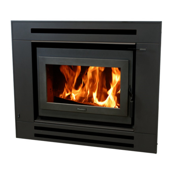
Masport I9000 Installation Instructions Manual
Hide thumbs
Also See for I9000:
- Installation instructions manual (6 pages) ,
- Installation insrtuctions (8 pages) ,
- Installation instructions manual (13 pages)
Advertisement
Quick Links
MASPORT I9000 BUILT-IN FIRE
INSTALLATION INSTRUCTIONS
Manufactured in New Zealand by:
GLEN DIMPLEX AUSTRALASIA LIMITED
38 Harris Road, East Tamaki
Auckland
Ph: 0800 666 2824
Fax: 09 274 8472
Email: sales@glendimplex.co.nz
Web: www.glendimplex.co.nz
15.10.2014
Part. No. 593359
Distributed in Australia by:
GLEN DIMPLEX AUSTRALIA PTY LIMITED
Unit 1, 21 Lionel Road, Mount Waverley
Victoria, 3149
Ph: 1 300 566 816
Fax: 1 800 058 900
Email: sales@glendimplex.com.au
Web: www.glendimplex.com.au
1
Advertisement

Summary of Contents for Masport I9000
-
Page 1: Installation Instructions
MASPORT I9000 BUILT-IN FIRE INSTALLATION INSTRUCTIONS Manufactured in New Zealand by: Distributed in Australia by: GLEN DIMPLEX AUSTRALASIA LIMITED GLEN DIMPLEX AUSTRALIA PTY LIMITED 38 Harris Road, East Tamaki Unit 1, 21 Lionel Road, Mount Waverley Auckland Victoria, 3149 Ph: 0800 666 2824... - Page 3 The model I9000 has been tested to demonstrate compliance with current general emission re- quirements in Australia and New Zealand, but some areas have stricter limits. So check before pur-...
- Page 4 SULT IN HAZARDOUS CONDITIONS. WHERE SUCH ACTION IS CONSIDERED, THE MANU- FACTURER SHOULD BE CONSULTED IN THE FIRST INSTANCE. NOTE The following instructions cover the installation of the model I9000 Built-In Fire complete with a ‘zero clearance’ metal shielding box, ‘zero clearance’ fascia and special ‘zero clearance’ flue kit.
-
Page 5: Installation Requirements
INSTALLATION REQUIREMENTS INSTALLATIONS- FLOOR TO CEILING ENCLOSURE: Inspect the house construction at the proposed installation position to verify that the flue cas- ing (250mm diameter, plus 25mm clearance all around) can pass through the ceiling space without requiring the removal of essential roof or ceiling support beams. The flue centerline will be 300mm from the rear wall and any side wall adjacent to that of the fire recess must be at east 760mm from the centre line of the flue. - Page 6 tions. Glen Dimplex accepts no responsibility for the deterioration of surfaces of finish- es. It is usually convenient to carry the same material right up to the ceiling level. At the lower edge, drill (4.5mm diameter) holes into the metal support angle through the holes in the top flange of the shielding box and fasten with the self threading screws provided.
- Page 7 tion of the firebox cabinet. Attach the two centralizing angles to the side panels of the firebox cabinet, flanges facing for- ward and outwards. Use two screws provided for each bracket. Slide the firebox cabinet into the shielding box. Centralize it and secure the restraint brackets to the shielding box flanges.
- Page 8 Finish the floor protector by installing an edge trim if desired. NOTES TO VENT OPENING: The opening must be covered with an appro- priate mesh or similar to prevent vermin etc entering the enclosure. A sample opening with 13’300mm² net open area is shown below. Fig.
- Page 9 NOTES TO VENT OPENING: The opening must be covered with an ap- propriate mesh or similar to prevent vermin etc entering the enclosure. A sample open- ing with 13’300mm² net open area is shown below. Fig. 6 INSTALLATION- ELEVATED NOTES TO VENT OPENING: The opening must be covered with an ap- propriate mesh or similar to prevent vermin etc entering the enclosure.
- Page 10 Fig. 8 HEIGHTS OF FLUE PIPE & CASINGS FOR SFP COMBINATION COWL ( Fixed Bracket) Fig. 9 HEIGHTS OF FLUE PIPE & CASINGS FOR SFP STANDARD CASING COVER & COWL & SFP TOP FLUE PIPE SPACER BRACKET...
- Page 11 Fig. 10 HEIGHTS OF FLUE PIPE & CASINGS FOR STANDARD CASING COVER & COWL & TOP FLUE PIPE SPAC- ER BRACKET BY GLEN DIMPLEX FALSE CHIMNEY VENTED THROUGH 150-130 CASING COVER NOTE: It is very important that the space between the flue pipe and the inner casing and the space between the inner casing and the outer casing are ventilated at the top.
-
Page 12: External Installations
NOTES FOR VARIATIONS CONCRETE FLOORS The above instructions assume that the appliance is being installed on a heat sensitive floor such as timber or particle board. Where the floor is not heat sensitive (e.g. concrete), the insulating floor pro- tector may be omitted. However, if heat sensitive floor coverings (e.g.carpet) are fitted it will be nec- essary to keep them at a safe distance. -
Page 13: Installing The Fascia
INSTALLING THE FASCIA Unpack fascia and lay flat on floor front face up, careful not to scratch the paintwork. Remove the vent cover panel (item 1) which will be just above the door on the final installation. It is secured with two screws. - Page 14 Connect the air slide extension lever with two self tapping screws to the air slide. The extension lever protrudes out in the front of the fascia. There are slots in the air slide extension to allow for optimum height adjustment . Fig.


Need help?
Do you have a question about the I9000 and is the answer not in the manual?
Questions and answers