Table of Contents
Advertisement
Quick Links
Download this manual
See also:
User Manual
Advertisement
Table of Contents

Related Manuals for thomann E-400


Summary of Contents for thomann E-400
- Page 1 E-400 power amplifier user manual...
- Page 2 Musikhaus Thomann e.K. Treppendorf 30 96138 Burgebrach Germany Telephone: (09546) 9223-0 E-mail: info@thomann.de Internet: www.thomann.de 22.10.2013...
-
Page 3: Table Of Contents
Table of contents Table of contents General notes............................... 4 Safety notes..............................7 Features............................... 12 Installation and operation........................13 Connections and controls........................17 Technical data............................23 Plug and connection assignment....................25 Cleaning............................... 30 Protecting the environment......................31 E-400... -
Page 4: General Notes
General notes General notes This user manual contains important information on safe operation of the device. Read and follow all safety notes and all instructions. Save this manual for future reference. Make sure that it is available to all persons using this device. If you sell the device, include the manual for the next owner. - Page 5 NOTICE! This combination of symbol and signal word indicates a possible dangerous situation that can result in material and environmental damage if it is not avoided. Warning signs Type of danger Warning – high-voltage. E-400...
- Page 6 General notes Warning signs Type of danger Warning – danger zone. power amplifier...
-
Page 7: Safety Notes
Choking hazard! Ensure that children do not detach any small parts (e.g. knobs or the like) from the unit. They could swallow the pieces and choke! Never let children unattended use electrical devices. E-400... - Page 8 Safety notes DANGER! Electric shock caused by high voltages inside Within the device there are areas where high voltages may be present. Never remove any covers. There are no user-serviceable parts inside. DANGER! Electric shock caused by short-circuit Always use proper ready-made insulated mains cabling (power cord) with a pro‐ tective contact plug.
- Page 9 NOTICE! Risk of fire Do not cover the device nor any ventilation slots. Do not place the device near any direct heat source. Keep the device away from naked flames. E-400...
- Page 10 Safety notes NOTICE! Operating conditions This device has been designed for indoor use only. To prevent damage, never expose the device to any liquid or moisture. Avoid direct sunlight, heavy dirt, and strong vibrations. NOTICE! Power supply Before connecting the device, ensure that the input voltage (AC outlet) matches the voltage rating of the device and that the AC outlet is protected by a residual current circuit breaker.
- Page 11 When installing the power amplifier into a rack, you should place it in the lowest position, and further equipment such as pre-amplifiers in the highest position. E-400...
-
Page 12: Features
Features Features Small mounting depth of only 308 mm 2 × 190 W at 4 Ω, 2 × 120 W at 8 Ω Inputs: XLR, (balanced) phone jack and RCA Outputs: NL4 (Speakon) and binding-post connectors for speakers Protective circuits: DC, short-circuit, overtemperature, limiter Automatic standby (can be disabled) power amplifier... -
Page 13: Installation And Operation
DANGER! Electric shock caused by high voltages at the power amplifier output The output voltages of modern high-performance amplifiers may result in death or serious injury. Never touch the bare ends of loudspeaker cables when the amplifier is on. E-400... - Page 14 Installation and operation NOTICE! Magnetic fields The device generates strong magnetic fields that can interfere with the function of poorly shielded devices. The strongest magnetic fields are directly above and below the power amplifier. Therefore, never place sensitive devices such as pre- amplifiers, radio transmission systems, or tape decks directly above or below the power amplifier.
- Page 15 The two amplifier channels are internally connected in such a way that twice the output power is available. Only the input signal from channel A is amplified and loudspeakers are connected only to the correspondingly marked output. The volume is controlled via the control knob for channel A. E-400...
- Page 16 For detailed information related to this topic please refer to our Online Guide ‘PA Speakers’ (www.thomann.de). Rack mounting The device has been designed for rack mounting in a standard 19-inch rack; it occupies two rack units.
-
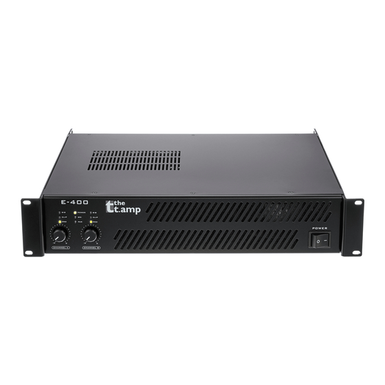
Page 17: Connections And Controls
Connections and controls Connections and controls Front panel E-400... - Page 18 Connections and controls 1 POWER Power on/off switch. Switches the device on and off. 2 LED panel Indicates the presence of an input signal. CLIP Lights under the following conditions: Channel overdrive. In this case, reduce the volume until the LED turns off. Short-circuit at the output.
- Page 19 In standby mode, the LED lights red. When the unit receives a signal again, it switches back to normal mode and the LED lights green again. Lights when the device is operated in parallel mode. Lights when the device is operated in bridged mode. 3, 4 CHANNEL A, Volume control for the respective channels. CHANNEL B E-400...
- Page 20 Connections and controls Rear panel 5 Plug for mains cable and fuse holder 6 ERP ON | OFF This switch enables/disables the standby feature. If enabled, the unit automatically enters the standby mode when no input signal is present for at least five minutes. power amplifier...
- Page 21 If there are hums due to a ground loop, you can use this switch to disconnect the protective earth connector from the signal ground of the device. 10 LIMIT Limits the output level such that maximum distortion is 5 %. 11 Selector switch for operating mode PAR: Parallel mode STR: Stereo mode BR: Bridged mode E-400...
- Page 22 Connections and controls 12 Selector switch for input sensitivity 13, 14 INPUT Input channel B, A Female XLR panel connector ¼-inch (6.35-mm) jack (balanced or unbalanced) RCA jack power amplifier...
-
Page 23: Technical Data
< 0.03 % power output Inputs Female XLR panel connectors, ¼-inch (6.35-mm) jacks, RCA jacks Input impedance 20 kΩ (balanced), 10 kΩ (unbalanced) Outputs speakON panel connector, screw terminals Mains power supply 220 – 240 V (AC), 50 Hz E-400... - Page 24 Technical data Power consumption 1100 W Dimensions (W × D × H) 482 mm × 317 mm × 88 mm Weight 8.3 kg power amplifier...
-
Page 25: Plug And Connection Assignment
In a professional environment, therefore, the balanced transmission is preferred, because this enables an undisturbed transmission of signals over long distances. In addition to the conduc‐ tors ‘Ground’ and ‘Signal’, in a balanced transmission a second core is added. This also transfers the signal, but phase-shifted by 180°. E-400... - Page 26 Plug and connection assignment Since the interference affects both cores equally, by subtracting the phase-shifted signals, the interfering signal is completely neutralized. The result is a pure signal without any noise inter‐ ference. 1/4" TS phone plug (mono, unbalanced) Signal Ground, shielding 1/4"...
- Page 27 Plug and connection assignment 1/4" TRS phone plug (stereo, unbalanced) Signal (left) Signal (right) Ground XLR plug (balanced) Ground, shielding Signal (in phase, +) Signal (out of phase, –) E-400...
- Page 28 Plug and connection assignment XLR plug (unbalanced) Ground, shielding Signal Bridged to pin 1 NL4 mounting connectors 1, + Signal 1 (in phase) 1, – Signal 1 (180 degree phase shift) 2, + Signal 2 (in phase) 2, – Signal 2 (180 degree phase shift) power amplifier...
- Page 29 Plug and connection assignment RCA connection Drawing and table indicate the pin assignment of an RCA plug. Signal Ground, shielding E-400...
-
Page 30: Cleaning
Cleaning Cleaning Fan grids The fan grids of the device must be cleaned on a regular basis to remove dust and dirt. Before cleaning, switch off the device and disconnect AC-powered devices from the mains. Use a lint- free damp cloth for cleaning. Never use solvents or alcohol for cleaning. power amplifier... -
Page 31: Protecting The Environment
Dispose of this device through an approved waste disposal firm or through your local waste facility. When discarding the device, comply with the rules and regulations that apply in your country. If in doubt, consult your local waste disposal facility. E-400... - Page 32 Notes power amplifier...
- Page 33 Notes E-400...
- Page 34 Notes power amplifier...
- Page 36 Musikhaus Thomann e.K. · Treppendorf 30 · 96138 Burgebrach · Germany · www.thomann.de...
Need help?
Do you have a question about the E-400 and is the answer not in the manual?
Questions and answers