Table of Contents
Advertisement
Quick Links
Advertisement
Table of Contents

Related Manuals for thomann the t.amp E-400


Summary of Contents for thomann the t.amp E-400
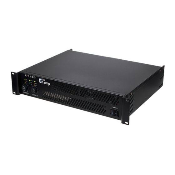
- Page 1 E-400, E-800, E-1200, E-1500 Power Amplifier...
- Page 2 Thomann GmbH Hans-Thomann-Straße 1 96138 Burgebrach Germany Telephone: +49 (0) 9546 9223-0 Internet: www.thomann.de 08.05.2024, ID: 173888, 173889, 460282, 460283 (V6)
-
Page 3: Table Of Contents
Table of contents Table of contents General information..........................5 1.1 Symbols and signal words....................... 5 Safety instructions............................. 7 Features............................... 10 Installation and starting up........................ 11 Connections and operating elements................... 15 Technical specifications........................23 Plug and connection assignment....................32 Cleaning............................... 36 Protecting the environment...................... - Page 4 E-400, E-800, E-1200, E-1500 Power Amplifier...
-
Page 5: General Information
Our products and documentation are subject to a process of continuous development. They are therefore subject to change. Please refer to the latest version of the documentation, which is ready for download under www.thomann.de. 1.1 Symbols and signal words In this section you will find an overview of the meaning of symbols and signal words that are used in this document. - Page 6 General information Signal word Meaning DANGER! This combination of symbol and signal word indicates an immediate dangerous situation that will result in death or serious injury if it is not avoided. WARNING! This combination of symbol and signal word indicates a pos‐ sible dangerous situation that can result in death or serious injury if it is not avoided.
-
Page 7: Safety Instructions
Safety instructions Safety instructions Intended use This device amplifies electric audio frequency signals to operate passive speakers. Use the device only as described in this user manual. Any other use or use under other operating con‐ ditions is considered to be improper and may result in personal injury or property damage. No liability will be assumed for damages resulting from improper use. - Page 8 Safety instructions DANGER! Danger to life due to electric current! A short circuit could lead to a fire hazard and risk of death. Always use proper ready-made insulated triple-core mains cable with a safety plug. Do not modify the mains cable or the plug. In case of isolation damage, disconnect immediately the power supply and arrange repair.
- Page 9 Safety instructions NOTICE! Damage to the device due to high voltages! The device can be damaged if it is operated with the incorrect voltage or if high voltage peaks occur. In the worst case, excess vol‐ tages can also cause a risk of injury and fires. Make sure that the voltage specification on the device matches the local power grid before plugging in the device.
-
Page 10: Features
Features Features Shallow installation depth Inputs: XLR, phone jack (balanced) and cinch (only for item no. 173888) Outputs: Speaker Twist and terminal clamps for speakers Protection circuits: DC, short circuit, over-temperature protection, limiter Standby function, can be deactivated (only in item no. 173888 and item no. 173889) E-400, E-800, E-1200, E-1500 Power Amplifier... -
Page 11: Installation And Starting Up
Installation and starting up Installation and starting up Unpack and check carefully there is no transportation damage before using the unit. Keep the equipment packaging. To fully protect the product against vibration, dust and moisture during transportation or storage use the original packaging or your own packaging material suitable for transport or storage, respectively. - Page 12 Installation and starting up NOTICE! Interference with nearby electrical devices due to magnetic fields! The device generates strong magnetic fields that can interfere with the function of poorly shielded devices. The magnetic fields are strongest directly above and below the Power Amplifier. You should therefore never place sensitive devices such as pre-amplifiers, radio transmission systems, or tape decks directly above or below the Power Amplifier.
- Page 13 Installation and starting up Possible operation modes Depending on the individual application, the amplifier can be used in different operation modes: Stereo mode The two amplifier channels operate independently of one another, either channel (A and B) is amplified and connected to loudspeakers, the volume can be controlled separately for the two outputs.
- Page 14 For detailed information related to this topic please refer to our Online Guide ‘PA Speakers’ (www.thomann.de). Rack mounting The device has been designed for rack mounting in a standard 19-inch rack; it occupies two rack units.
-
Page 15: Connections And Operating Elements
Connections and operating elements Connections and operating elements Front panel ö 1 [POWER] | Mains switch. Turns the device on and off. 2 LED panel [SIG] | Indicates the presence of an input signal. E-400, E-800, E-1200, E-1500 Power Amplifier... - Page 16 Connections and operating elements [CLIP] | Lights under the following conditions: Channel overload Reduce in this case the volume until the LED goes out. Output short circuit Turn off the device immediately, correct the short circuit and turn on the device again. [PRO] | Lights under the following conditions: Three to five seconds after switching on or off when the device is in an unstable condition.
- Page 17 Connections and operating elements Rear panel E-400 STANDBY & * + , - 5 IEC chassis plug with fuse holder 6 [ON] [OFF] [STANDBY] | On / off switch for standby function. If the standby function is enabled, the device automati‐ cally switches to standby mode after fifteen minutes without any input signal.
- Page 18 Connections and operating elements 7, 8 [OUTPUT] | Output channel B, A Speaker Twist chassis connector for speaker output (1+, 2+: positive; 1–, 2–: negative) Screw terminals 9 [GROUND] [LIFT] | Ground / lift switch. If hum is caused by a ground loop, you can use this switch to disconnect the connection between the earth pin of the device and the signal ground of the device.
- Page 19 Connections and operating elements Rear panel E-800 STANDBY PUSH PUSH BREAKER Bridge Stereo Parallel 1.4V 26dB 0.77V LIMITER 15 Power cord 16 [ON] [OFF] [STANDBY] | On / off switch for standby function. If the standby function is enabled, the device automati‐ cally switches to standby mode after fifteen minutes without any input signal.
- Page 20 Connections and operating elements 17 [BREAKER] | Resettable fuse. The fuse switches off when the power consumption of the power amplifier is too high. Once the problem is resolved, the fuse is automatically reset and the device is ready for use again. The switch can be used to force the reset.
- Page 21 Connections and operating elements Rear panel E-1200, E-1500 PUSH PUSH < > 27 IEC panel plug 28, 29 [OUTPUT] | Output channel B, A Speaker Twist chassis connector for speaker output (1+, 2+: positive; 1–, 2–: negative) Screw terminals E-400, E-800, E-1200, E-1500 Power Amplifier...
- Page 22 Connections and operating elements 30, 32 [INPUT] | Input channel B, A XLR chassis socket (male) XLR chassis socket (female) 31 Selector switch for operating mode [PAR]: Parallel mode [STR]: Stereo mode [BRI]: Bridged mode E-400, E-800, E-1200, E-1500 Power Amplifier...
-
Page 23: Technical Specifications
Technical specifications Technical specifications E-400 (item no. 173888) Amplifier class Input connections 1 × Rubber panel plug C14 2 × XLR socket, 3-pin 2 × 6.35-mm jack socket 2 × cinch socket Input impedance 20 kΩ (balanced) 10 kΩ (unbalanced) Output connections 2 ×... - Page 24 Technical specifications Frequency response 20 Hz…20 kHz, ±0.1 dB Signal-to-noise ratio ≤ 90 dB Total harmonic distortion (THD) 0.01% at -3 dBu Damping factor (1 kHz, 8 Ω) > 220 Sensitivity 0.775 V / 26 dB / … 1.4 V Gain 34 dB (0.77 V), 28 dB (1.4 V) Crosstalk at rated power @ 8 Ω, 1 kHz...
- Page 25 Technical specifications E-800 (item no. 173889) Amplifier class H, 2 stages Input connections 2 × XLR socket, 3-pin 2 × 6.35-mm jack socket Input impedance 20 kΩ (balanced) 10 kΩ (unbalanced) Output connections 2 × Speaker Twist panel connector 4 × screw terminal Output power Power @ 1 kHz, 1 % THD+N Continuous...
- Page 26 Technical specifications Sensitivity 0.775 V / 26 dB / … 1.4 V Gain 36 dB (0.77 V), 31 dB (1.4 V) Crosstalk at rated power @ 8 Ω, 1 kHz -53 dB Maximum power consumption @ 1750 W @ 4 Ω 1 kHz, 0 dBu, 230 V 950 W @ 8 Ω...
- Page 27 Technical specifications E-1200 (item no. 460282) Amplifier class Input connections 1 × Rubber panel plug C14 4 × XLR socket, 3-pin Input impedance 20 kΩ (balanced) 10 kΩ (unbalanced) Output connections 2 × Speaker Twist panel connector 4 × screw terminal Output power Power @ 1 kHz, 1 % THD+N Continuous...
- Page 28 Technical specifications Sensitivity 0.77 V / 26 dB / … 1.4 V Gain 41 dB Crosstalk at rated power @ 8 Ω, 1 kHz -61 dB Maximum power consumption @ 3200 W @ 4 Ω 1 kHz, 0 dBu, 230 V 2000 W @ 8 Ω...
- Page 29 Technical specifications E-1500 (item no. 460283) Amplifier class Input connections 1 × Rubber panel plug C14 4 × XLR socket, 3-pin Input impedance 20 kΩ (balanced) 10 kΩ (unbalanced) Output connections 2 × Speaker Twist panel connector 4 × screw terminal Output power Power @ 1 kHz, 1 % THD+N Continuous...
- Page 30 Technical specifications Sensitivity 0.77 V / 26 dB / … 1.4 V Gain 41 dB Crosstalk at rated power @ 8 Ω, 1 kHz -60 dB Maximum power consumption @ 4200 W @ 4 Ω 1 kHz, 0 dBu, 230 V 2500 W @ 8 Ω...
- Page 31 Technical specifications Further information 2-Ω stable DSP / crossover Convection cooling E-400, E-800, E-1200, E-1500 Power Amplifier...
-
Page 32: Plug And Connection Assignment
Plug and connection assignment Plug and connection assignment Introduction This chapter will help you select the right cables and plugs to connect your valuable equip‐ ment in such a way that a perfect sound experience is ensured. Please note these advices, because especially in ‘Sound & Light’ caution is indicated: Even if a plug fits into the socket, an incorrect connection may result in a destroyed power amp, a short circuit or ‘just’... - Page 33 Plug and connection assignment 1/4" TS phone plug (mono, unbalanced) Signal Ground, shielding 1/4" TRS phone plug (mono, bal‐ anced) Signal (in phase, +) Signal (out of phase, –) Ground 1/4" TRS phone plug (stereo, unbalanced) Signal (left) Signal (right) Ground E-400, E-800, E-1200, E-1500 Power Amplifier...
- Page 34 Plug and connection assignment XLR plug (balanced) Ground, shielding Signal (in phase, +) Signal (out of phase, –) Shielding on plug housing (option) XLR plug (unbalanced) Ground, shielding Signal Bridged to pin 1 E-400, E-800, E-1200, E-1500 Power Amplifier...
- Page 35 Plug and connection assignment Speaker Twist chassis connector 1, + Signal 1 (in phase) 1, – Signal 1 (out of phase) 2, + Signal 2 (in phase) 2, – Signal 2 (out of phase) ö RCA connection Drawing and table indicate the pin assignment of an RCA plug. Signal Ground, shielding E-400, E-800, E-1200, E-1500...
-
Page 36: Cleaning
Cleaning Cleaning Fan grids The fan grids of the device must be cleaned of any contamination, such as dust, etc. on a reg‐ ular basis. Before cleaning, switch off the device and disconnect mains-operated devices from the mains. Only use pH-neutral, solvent-free and non-abrasive cleaning agents. Clean the unit with a slightly damp lint-free cloth. -
Page 37: Protecting The Environment
Protecting the environment Protecting the environment Disposal of the packing material Environmentally friendly materials have been chosen for the packaging. These materials can be sent for normal recycling. Ensure that plastic bags, packaging, etc. are disposed of in the proper manner. Do not dispose of these materials with your normal household waste, but make sure that they are collected for recycling. - Page 38 When disposing of the device, comply with the rules and regulations that apply in your country. You can also return your old device to Thomann GmbH at no charge. Check the current conditions on www.thomann.de.
- Page 40 Musikhaus Thomann · Hans-Thomann-Straße 1 · 96138 Burgebrach · Germany · www.thomann.de...
Need help?
Do you have a question about the the t.amp E-400 and is the answer not in the manual?
Questions and answers