Table of Contents
Advertisement
Advertisement
Table of Contents

Related Manuals for thomann the t.amp D4-500


Summary of Contents for thomann the t.amp D4-500
- Page 1 D4-500 digital power amplifier user manual...
- Page 2 Musikhaus Thomann Thomann GmbH Hans-Thomann-Straße 1 96138 Burgebrach Germany Telephone: +49 (0) 9546 9223-0 E-mail: info@thomann.de Internet: www.thomann.de 17.07.2015, ID: 218916 (V2)
-
Page 3: Table Of Contents
Table of contents Table of contents General information..........................4 1.1 Further information........................... 5 1.2 Notational conventions........................6 1.3 Symbols and signal words....................... 6 Safety instructions............................. 8 Features............................... 13 Installation and operation........................14 Connections and controls........................15 Current consumption..........................20 Technical specifications........................21 Plug and connection assignment.................... -
Page 4: General Information
General information General information This manual contains important instructions for the safe operation of the unit. Read and follow the safety instructions and all other instructions. Keep the manual for future reference. Make sure that it is available to all those using the device. If you sell the unit please make sure that the buyer also receives this manual. -
Page 5: Further Information
General information 1.1 Further information On our website (www.thomann.de) you will find lots of further information and details on the following points: Download This manual is also available as PDF file for you to download. Use the search function in the electronic version to find the topics of Keyword search interest for you quickly. -
Page 6: Notational Conventions
General information 1.2 Notational conventions This manual uses the following notational conventions: Letterings The letterings for connectors and controls are marked by square brackets and italics. Examples: [VOLUME] control, [Mono] button. Cross-references References to other locations in this manual are identified by an arrow and the specified page number. - Page 7 General information Signal word Meaning DANGER! This combination of symbol and signal word indicates an immediate dangerous situation that will result in death or serious injury if it is not avoided. CAUTION! This combination of symbol and signal word indicates a pos‐ sible dangerous situation that can result in minor injury if it is not avoided.
-
Page 8: Safety Instructions
Safety instructions Safety instructions Intended use This device amplifies electric audio frequency signals to operate passive speakers. Use the device only as described in this user manual. Any other use or use under other operating con‐ ditions is considered to be improper and may result in personal injury or property damage. No liability will be assumed for damages resulting from improper use. - Page 9 Safety instructions DANGER! Electric shock caused by high voltages inside Within the device there are areas where high voltages may be present. Never remove any covers. There are no user-serviceable parts inside. Do not use the device if covers, protectors or optical components are missing or damaged.
- Page 10 Safety instructions CAUTION! Possible hearing damage The device can produce volume levels that may cause temporary or permanent hearing impairment. Over an extended period of time, even levels that seem to be uncritical can cause hearing damage. Decrease the volume level immediately if you experience ringing in your ears or hearing impairment.
- Page 11 Safety instructions NOTICE! Operating conditions This device has been designed for indoor use only. To prevent damage, never expose the device to any liquid or moisture. Avoid direct sunlight, heavy dirt, and strong vibrations. NOTICE! Power supply Before connecting the device, ensure that the input voltage (AC outlet) matches the voltage rating of the device and that the AC outlet is protected by a residual current circuit breaker.
- Page 12 Safety instructions NOTICE! Magnetic fields The device generates strong magnetic fields that can interfere with the function of poorly shielded devices. The strongest magnetic fields are directly above and below the power amplifier. Therefore, never place sensitive devices such as pre- amplifiers, radio transmission systems, or tape decks directly above or below the power amplifier.
-
Page 13: Features
Features Features Output power 4 × 500 W @ 4 W – – 4 × 250 W @ 8 W 4 inputs, 4 outputs Frequency response 20 Hz to 20 kHz 19" rackable (1 RU, installation depth 240 mm) D4-500... -
Page 14: Installation And Operation
Installation and operation Installation and operation NOTICE! Possible staining The plasticiser contained in the rubber feet of this product may possibly react with the coating of your parquet, linoleum, laminate or PVC floor and after some time cause permanent dark stains. In case of doubt, do not put the rubber feet directly on the floor, but use felt-pad floor protectors or a carpet. -
Page 15: Connections And Controls
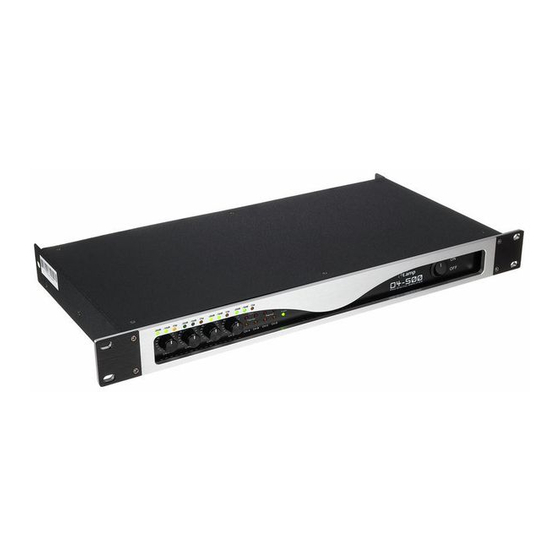
Connections and controls Connections and controls Front panel D4-500... - Page 16 Connections and controls 1 [ON | OFF] Main switch to turn the device on and off. 2 LED [Power] This LED indicates, that the unit is operational and lights up constantly as soon as the device is switched on. 3 LED [–10 dB] and [–20 dB] These LEDs indicate the intensity of the input signal (–10 dB or –20 dB).
- Page 17 Connections and controls 5 LED [Fault] Error indication for channels CH-A to CH-D. These LEDs light up when one of the protective circuits triggers (see Ä Chapter 7 ‘Technical specifications’ on page 21). When turning the device on, the LEDs light up for three seconds. During this time, there is no signal present at the output yet.
- Page 18 Connections and controls Rear panel digital power amplifier...
- Page 19 Connections and controls 8 IEC chassis connector. 9 [INPUT CH-A …-D] Lockable combo XLR/¼-inch connectors for signal inputs. 10 [OUTPUT CH-A …-D] Lockable NL4 mounting connectors for signal outputs. 11 [Stereo | Bridge] selector switch Switch for operating modes ‘Stereo’ (channels operate independently of each other) and ‘Bridge’ (two channels are interconnected to form one channel with double output).
-
Page 20: Current Consumption
Current consumption Current consumption The following table contains information on the typical current consumption depending on the output power level (root mean square value A ). All values based on a 230 V mains voltage and a 1 kHz input signal at 0 dB (sine). Load 1/8 nominal power 1/3 nominal power... -
Page 21: Technical Specifications
Technical specifications Technical specifications Rated output power @ 8 W 4 × 250 W (THD = 1 %, 1 kHz) Rated output power @ 4 W 4 × 500 W (THD = 1 %, 1 kHz) Max. voltage swing (RMS) 35 V (THD = 1 %, 1 kHz) Slew rate (1 kHz) 26 V/ms... - Page 22 Technical specifications Signal-to-noise ratio 107 dB (A-weighted) Protective circuits VHF, direct voltage, temperature, short circuit, Undervoltage, overcurrent, lim‐ iter Operating voltage supply AC 230 V , 50/60 Hz Power consumption Ä Chapter 6 ‘Current consumption’ on page 20 Dimensions 1 RU in a 19" rack, installation depth 240 mm Weight 4.6 kg digital power amplifier...
-
Page 23: Plug And Connection Assignment
Plug and connection assignment Plug and connection assignment Introduction This chapter will help you select the right cables and plugs to connect your valuable equip‐ ment in such a way that a perfect sound experience is ensured. Please note these advices, because especially in ‘Sound & Light’ caution is indicated: Even if a plug fits into the socket, an incorrect connection may result in a destroyed power amp, a short circuit or ‘just’... - Page 24 Plug and connection assignment Since the interference affects both cores equally, by subtracting the phase-shifted signals, the interfering signal is completely neutralized. The result is a pure signal without any noise inter‐ ference. 1/4" TS phone plug (mono, unbalanced) Signal Ground, shielding 1/4"...
- Page 25 Plug and connection assignment 1/4" TRS phone plug (stereo, unbalanced) Signal (left) Signal (right) Ground XLR plug (balanced) Ground, shielding Signal (in phase, +) Signal (out of phase, –) D4-500...
- Page 26 Plug and connection assignment NL4 mounting connectors 1, + Signal 1 (in phase) 1, – Signal 1 (180 degree phase shift) 2, + Signal 2 (in phase) 2, – Signal 2 (180 degree phase shift) digital power amplifier...
-
Page 27: Cleaning
Cleaning Cleaning Fan grids The fan grids of the device must be cleaned on a regular basis to remove dust and dirt. Before cleaning, switch off the device and disconnect AC-powered devices from the mains. Use a lint- free damp cloth for cleaning. Never use solvents or alcohol for cleaning. D4-500... -
Page 28: Protecting The Environment
Protecting the environment Protecting the environment Disposal of the packaging mate‐ rial For the transport and protective packaging, environmentally friendly materials have been chosen that can be supplied to normal recycling. Ensure that plastic bags, packaging, etc. are properly disposed of. Do not just dispose of these materials with your normal household waste, but make sure that they are collected for recycling. - Page 29 Notes D4-500...
- Page 30 Notes digital power amplifier...
- Page 32 Musikhaus Thomann · Hans-Thomann-Straße 1 · 96138 Burgebrach · Germany · www.thomann.de...
Need help?
Do you have a question about the the t.amp D4-500 and is the answer not in the manual?
Questions and answers