
Related Manuals for Eaton Pulsar Series 650


Summary of Contents for Eaton Pulsar Series 650
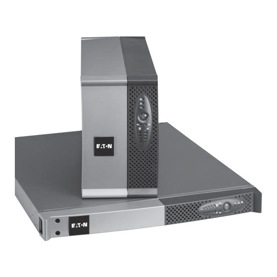
- Page 1 Evolution 650/650 Rack 1U 850/850 Rack 1U 1150/1150 Rack 1U 1550/1550 Rack 1U Installation and user manual Pulsar Series...
- Page 2 34008235EN/AC - Page 2...
-
Page 3: Environmental Protection
Before installing Evolution, please read the booklet presenting the safety instructions. Then follow the indications in this manual. To discover the entire range of EATON products and the options available for the Evolution range, we invite you to visit our web site at www.eaton.com or contact your EATON representative. - Page 4 Introduction Pictograms Important instructions that must always be followed. Information, advice, help. Visual indication. Action. Audio signal. In the illustrations on the following pages, the symbols below are used: LED off LED on LED flashing 34008235EN/AC - Page 4...
-
Page 5: Table Of Contents
Contents Presentation Standard positions ........................6 Tower models ..........................6 Rack models........................... 6 Rear panels ........................... 7 Evolution 650/850/1150/1550 ......................7 Evolution 650/850/1150/1550 Rack ....................7 Control panel..........................7 Installation Unpacking and contents check....................8 Installation of tower model......................9 Installation of rack model ...................... -
Page 6: Presentation
1. Presentation 1.1 Standard positions Tower models Dimensions (H x W x D) in mm Evolution 650 234 x 147 x 418 Evolution 850 234 x 147 x 418 Evolution 1150 234 x 147 x 418 Evolution 1550 234 x 147 x 492 Weights in kg Evolution 650 Evolution 850... -
Page 7: Rear Panels
1. Presentation 1.2 Rear panels Evolution 650/850/1150/1550 (1) Slot for optional communication card (2) Socket for connection to AC-power source (3) 2 outlets for connection of equipment 230V/10A Max (4) RS232 communication port (5) 2 programmable outlets (1 and 2) for Ue/In/Eing connection of equipment (6) USB communication port... -
Page 8: Installation
2. Installation 2.1 Unpacking and contents check (16) Evolution UPS, tower or rack model (17) 2 connection cables for the protected equipment (18) Documentation (19) Solution-Pac CD-ROM (20) RS232 communication cable (21) USB communication cable (22) Mounting kit for 19-inch bays (rack model only, except 650 Rack) (23) System to secure power plugs (rack model only) Packing materials must be disposed of in compliance with all local regulations concerning waste. -
Page 9: Installation Of Tower Model
2. Installation 2.2 Installation of tower model 2.3 Installation of rack model Follow steps 1 to 4 for module mounting on the rails. The rails and necessary hardware are supplied by EATON. 34008235EN/AC - Page 9... -
Page 10: Installation Of The 650 Rack Model
2. Installation 2.4 Installation of the 650 rack model Follow steps 1 to 3 for rack mounting. The necessary hardware is supplied by EATON. 34008235EN/AC - Page 10... -
Page 11: Communication Ports
I max 6.5A USB (6) or RS232 (4) communication port on the UPS. The UPS can now communicate with EATON power management software. Installation of the communication cards (optional) It is not necessary to shutdown the UPS before installing a communication card. -
Page 12: Equipment Connections
(5) (1 and 2). To program shutdown of outlets (5) during operation on battery power and thus optimise the available backup time, the EATON communication software is required. (1) Cable characteristics: 250 V - 10 A (CSA , type HO5). -
Page 13: Operation
3. Operation 3.1 Start-up and normal operation Press button (10) for approximately 1 second. ◗ The buzzer beeps once and all the LEDs go ON simultaneously. ◗ If AC input power is available, button (10) and LED (13) are ON. The load is supplied by the AC-power source. -
Page 14: Ups Shutdown
3. Operation 3.4 UPS shutdown Press button (10) for approximately 2 seconds. The devices connected to the UPS are no longer supplied. 3.5 UPS remote-control functions Evolution offers a choice between two remote control functions. ◗ RPO (Remote Power Off) allows a remote contact to be used to disconnect all the equipment connected to the UPS. -
Page 15: Measurements And Personalisation
4. Access to measurements and personalisation data ◗ Insert the Solution-Pac CD-ROM in the drive. ◗ On the first navigation screen, select "Point to Point solution" and follow the instructions on how to install the Personal Solution-Pac software. ◗ Then select "Settings", "Advanced settings" and "UPS settings". Note that the Linux/Unix/MacOS versions of Personal Solution-Pac software do not offer this possibility. -
Page 16: Maintenance
5. Maintenance 5.1 Troubleshooting Indication Diagnostic Correction When the UPS is started using button The remote power off (RPO) Set the contact back to its normal (10), all the LEDs go ON once and the contact has been activated to shut position and press button (10) to buzzer beeps once, then LED (14) down the UPS and now prevents... -
Page 17: Mounting The New Battery Module
Mounting the new battery module Carry out the above instructions in reverse order. ◗ To ensure safety and high performance, use only batteries supplied by EATON. ◗ Take care to firmly press together the two parts of the connector during remounting. -
Page 18: Mounting The New Battery Module
Take care to firmly press together the two parts of the connector during remounting. 5.4 Training centre To fully master operation of your EATON product and carry out level 1 servicing, see our complete range of technical training courses, available in both French and English. -
Page 19: Appendices
6. Appendices 6.1 Technical specifications Filter Transformer Charger Inverter ”AVR” Battery Evolution 650 / 650 Rack 850 / 850 Rack 1150 / 1150 Rack 1550 / 1550 Rack Output power 650 VA / 850 VA / 1150 VA / 1550 VA / 420 W 600 W 770 W... -
Page 20: Glossary
6. Appendices 6.2 Glossary Backup time Time during which the load can be supplied by the UPS operating on battery power. Battery test Internal UPS test to check battery status. Booster mode Automatic UPS mode that steps up the AC voltage if it is too low, to a level above the personalised set-point, without discharging the battery. - Page 21 Notes 34008235EN/AC - Page 21...
- Page 22 34008235EN/AC...
Need help?
Do you have a question about the Pulsar Series 650 and is the answer not in the manual?
Questions and answers