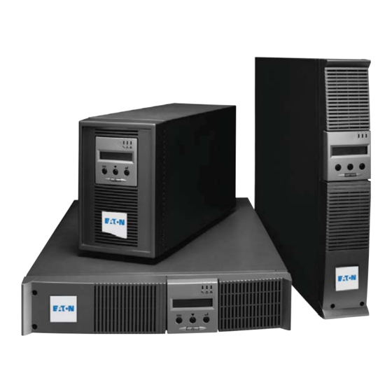
Eaton EX 700 Installation And User Manual
Eaton ex range pulsar series ups
Hide thumbs
Also See for EX 700:
- Installation and user manual (120 pages) ,
- Installation and user manual (200 pages)

Subscribe to Our Youtube Channel
Related Manuals for Eaton EX 700


Summary of Contents for Eaton EX 700
- Page 1 700 - 1000 - 1500 1000 RT - 1500 RT EXB 1000 - 1500 EXB 1000 - 1500 RT Installation and user manual Pulsar Series...
- Page 2 34008097EN/AE - Page 2...
-
Page 3: Environmental Protection
Before installing EX, please read the booklet on the required safety instructions. Then follow the indications in this manual. To discover the entire range of EATON products and the options available for the EX range, we invite you to visit our web site at www.eaton.com or contact your EATON representative. - Page 4 Introduction Pictograms Important instructions that must always be followed. Information, advice, help. Visual indication. Action. Audio signal. In the illustrations on the following pages, the symbols below are used: LED off LED on LED flashing 34008097EN/AE - Page 4...
-
Page 5: Table Of Contents
Standard positions ........................6 Tower position..........................6 Rack position..........................6 Rear panels ........................... 7 EX 700 / 1000 / 1500........................7 EX 1000 RT / 1500 RT ........................7 EX EXB (optional battery module) ....................7 EX EXB RT (optional battery module)..................... 8 Control panel.......................... -
Page 6: Presentation
1. Presentation 1.1 Standard positions Tower position Dimensions (H x W x D) in mm EX 700 242 x 153 x 440 EX 1000 242 x 153 x 440 EX 1000 RT 86,5 x 438 x 483 EX 1500 242 x 153 x 490... -
Page 7: Rear Panels
(1) USB communication port (2) RS232 and dry contacts communication port (3) Connector for automatic recognition of a battery EXB module (except on EX 700) (4) Slot for optional communication card (5) Connector for remote ON/OFF and RPO (Remote Power Off) control... -
Page 8: Ex Exb Rt (Optional Battery Module)
1. Presentation EX EXB RT (optional battery module) 1.3 Control panel (20) Load protected LED (21) Downgraded operation LED (22) Load not protected LED (23) Alphanumeric display (24) Escape (cancel) button (25) Scroll button (26) Enter (confirm) button (27) ON/OFF button for UPS and outlets 34008097EN/AE - Page 8... -
Page 9: Installation
2. Installation 2.1 Unpacking and contents check (30) EX 700, 1000, 1500 Elements supplied depending on the version or optional (31) EX 1000 RT, 1500 RT (37) Mounting kit for 19-inch bays (32) 2 connection cables for the protected equipment... -
Page 10: Installation Of The Rt Model In Tower Position
It is advised to install the battery EXB module(s) at the lowest position in the rack, then install the UPS above. Follow steps 1 to 4 for module mounting on the rails. The rails and necessary hardware (37) are supplied by EATON. 34008097EN/AE - Page 10... -
Page 11: Communication Ports
2 - Connect the other end of the communication cable (33) or (34) to the USB (1) or RS232 (2) communication port on the UPS. The UPS can now communicate with EATON power management software. RT model - Page 11 34008097EN/AE... -
Page 12: Installation Of The Communication Cards (Optional)
2. Installation Installation of the communication cards (optional) Tower model RT model It is not necessary to shutdown the UPS before installing a communication card. (4): Slot, with restricted access, for the communications-card. 1 - Remove the UPS cover (4) secured by screws. -
Page 13: Connection With A Flexpdu (Power Distribution Unit) Module
2. Installation 2.6 Connections with a Fle PDU (Power Distribution Unit) module (optional) RT model 1 - Connect the UPS socket (9) to the AC- power source using the power cable from the equipments to be protected. 2 - Connect the input socket on the FlexPDU module (48) to the UPS outlet (7) or (8) using the cable (40) IEC 10A/16A supplied. -
Page 14: Hotswap Mbp-Module Operation
3 outlets marked (8) and the non- priority loads to the 3 outlets marked (7) that can be programmed in pairs (1 and 2). To program the outlets, the EATON communications software is required. RT model Note. The UPS charges the battery as soon as it is connected to the AC-power source, even if button (27) is not pressed. -
Page 15: Operation
If UPS personalisation is desired, it is advised to enter the personalisation mode at this time. This mode may be entered using the buttons on the control panel or the Personal Solution-Pac software (Windows) included on the Solution-Pac CD-ROM provided by EATON. 3.2 Operation on batter power Transfer to battery power ◗... -
Page 16: Return Of Ac Power
3. Operation End of battery backup time ◗ All the LEDs go OFF. ◗ The audio alarms stops. The UPS is completely shut down. 3.3 Return of AC power Following an outage, the UPS restarts automatically when AC power returns (unless the restart function was disabled via UPS personalisation) and the load is again supplied. - Page 17 3. Operation RT model Tower model Remote control connection and test 1 - Check the UPS is shut down and the electrical supply network disconnected. 2 - Remove connector (5) by unfitting the screws. 3 - Connect a normally closed volt-free contact (60 Vdc / 30 Vac max, 20 mA max, 0.75 mm² cable cross section) between the two pins of connector (5), see diagram.
-
Page 18: Access To Measurements And Personalisation Data
4. Access to measurements and personalisation data 4.1 Displa menus arrangement Status and Alarms Status and Alarms Measurements UPS input measurements UPS output measurements Battery measurements Personalisation Local personalisation Output personalisation ON/OFF personalisation Battery personalisation 4.2 Access to measurements Press the scroll button (25) to access any status conditions and alarms, then the measurements for voltage, current, frequency, power output and battery backup time. -
Page 19: Personalisation Using External Software
Automatic detection of 13 to 200 Ah time number of battery modules Battery protection Enabled Disabled When function disabled, EATON against excessive warranty no longer applies. discharges 4.4 Personalisation using e ternal software ◗ Insert the Solution-Pac CD-ROM in the drive. ◗... -
Page 20: Maintenance
5. Maintenance 5.1 Troubleshooting If LED (21) or (22) is ON, a fault or an alarm has occurred. Use the escape button (24) to stop the audio alarm. Indication Diagnostic Correction The UPS does not start, The AC input power is not Check the UPS is correctly the alphanumeric display indicates: connected or is connected to the... -
Page 21: Troubleshooting A Ups Equipped With The Hotswap Mbp Module
5. Maintenance Troubleshooting a UPS equipped with the HotSwap MBP module Indication Diagnostic Correction The load is no longer supplied when ◗ The protected devices are Check the wiring between the UPS the rotary switch (49) on the connected to the UPS output and the HotSwap MBP module HotSwap MBP module is set to the instead of to the HotSwap MBP... - Page 22 5. Maintenance D - Remove the metal protection cover in front of the battery (two screws). E - Turn the connector. F - Pass the connector through the hole. G - Pull the plastic tab to remove the battery block and replace it. Tower model A - Put the front panel near the UPS.
-
Page 23: Mounting The New Battery Module
Mounting the new battery module Carry out the above instructions in reverse order. ◗ To ensure safety and high performance, use only batteries supplied by EATON. ◗ Take care to firmly press together the two parts of the connector during remounting. -
Page 24: Maintenance On A Ups Equipped With The Hotswap Mbp Module
5. Maintenance 5.3 Maintenance on a UPS equipped with the HotSwap MBP module RT model The HotSwap MBP module makes possible to service or even replace the UPS without affecting the connected loads (HotSwap function). Maintenance: 1 - Set switch (53) to the Bypass position. The red LED (52) on the HotSwap MBP module goes ON, indicating that the load is supplied directly with AC power. -
Page 25: Training Centre
5. Maintenance 5.4 Training centre To fully master operation of your EATON product and carry out level 1 servicing, see our complete range of technical training courses, available in both French and English. For further information, please visit our website: www.eaton.com... -
Page 26: Appendices
6. Appendices 6.1 Technical specifications EX 700 EX 1000 EX 1500 EX EXB EX 1000 RT EX 1500 RT EX EXB RT Output power 700 VA / 630 W 1000 VA / 900 W 1500 VA / 1350 W AC input power ◗... -
Page 27: Glossary
6. Appendices 6.2 Glossar Bypass AC input Bypass line from the AC-power source, controlled by the UPS, used to directly supply the load if an overload or a malfunction occurs on the UPS. Backup time Time during which the load can be supplied by the UPS operating on battery power. Battery test Internal UPS test to check battery status.
Need help?
Do you have a question about the EX 700 and is the answer not in the manual?
Questions and answers