Table of Contents
Advertisement
Advertisement
Table of Contents

Related Manuals for JR XP652


Summary of Contents for JR XP652
- Page 1 INSTRUCTION MANUAL FOR AIRPLANE AND HELICOPTER 6-CHANNEL COMPUTER RADIO...
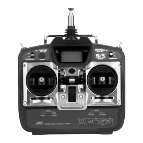
- Page 3 The functions decal will prove to be used when operating the XP652. a helpful guide for making program changes to your XP652 both in the shop and at the flying field. The four small decals help identify switch positions and use for helicopter and aircraft modes.
-
Page 4: Quick Start
Later, when you want to learn more about specific order to program each of the XF652's features. For features of the XP652, turn to the appropriate page(s) in modelers who want to get into the air fast, we have this manual for more detailed programming information. - Page 5 CLEAR ENTER INCREASE DECREASE MODE CHANNEL Press the MODE and CHANNEL buttons simultaneously to return to the model type display. Before flying check the direction of all control surfaces and that the travel is adjusted properly. XP652 MANUAL Quick Start...
- Page 6 T H R REV NORM – ENTER CLEAR INCREASE DECREASE MODE CHANNEL Press the INCREASE Press the CHANNEL button to select the button to reverse the direction of the channel channel you want to reverse. you selected. XP652 MANUAL Quick Start...
- Page 7 RVU appears on Press the CHANNEL the up and down positions. the screen. button until U or D A good place to start is appears on the screen. 35% up and 35% down. XP652 MANUAL Quick Start...
-
Page 8: Table Of Contents
IV. IMPORTANT INFORMATION Travel Adjustment General Notes Aileron to Rudder Mixing Daily Flight Checks Elevator to Flap Mixing Warranty Coverage Differential Repair Service Instructions Flap to Elevator Offset Trim Frequency Chart 7.10 Programmable Mixing (A, B, C) XP652 MANUAL Table of Contents... -
Page 9: Introduction
Introduction • USING THIS MANUAL The XP652 is a full feature introductory computer Blank data sheets are included at the end of both radio that can be used for airplanes and/or sections. Once you have input all the necessary data helicopters. -
Page 10: Servo Features
• 3-pole ferrite cored motor. • Ball bearing supported ouput shaft SERVO LAYOUT Servo Arm Retaining Screw Servo Mounting Flange Servo Arm/Horn Servo Output Shaft Rubber Grommets Servo Case Servo Eyelet Servo Mounting Flange Servo Lead w/Connector Rubber Grommets Top View XP652 MANUAL Introduction... -
Page 11: Servos
1.2Vx8 Nicad (9.6V) 600mah OUTPUT PULSE 1000-2000 (1500 Neutral) 1000-2000 (1500 Neutral) SERVO SPECIFICATIONS TYPE 517BB TORQUE (oz./in.) 40.3 SPEED WEIGHT 1.47 SIZE (in.) (W x L x H) 0.73 x 1.52 x 1.32 MOTOR 3-Pole Ferite XP652 MANUAL Introduction... -
Page 12: Receiver Specifications
CHARGING TIME 15 Hours 15 Hours AIRBORNE BATTERY PACK TYPE AIRPLANE HELICOPTER MODEL NUMBER 4N-600 4N-1000 VOLTAGE 4.8V 4.8V SIZE (in.) (W x L x H) 2.24 x 0.59 x 2.05 2.60 x 0.63 x 1.70 WEIGHT (oz.) XP652 MANUAL Introduction... -
Page 13: Battery Charging
OUTSIDE IS POSITIVE 1000mAh helicopter battery pack. Transmitter Only CHARGER PIGTAIL FOR TRANSMITTER The center pin on all JR remote control systems is BLACK TO POSITIVE negative. Therefore, the center pin on all JR chargers is negative, not positive. This is different from any other manufacturers’... -
Page 14: Trainer System
The XP652 features a built-in trainer system. The with all other current JR radios that have built-in transmitter can be used as either a master (trainer) trainer systems. An optional trainer cord is needed or as a slave (trainee). The XP652 is compatible (JRPA130). TRAINER D.S.C. -
Page 15: Transmitter Controls
Elevator Channel active only when the throttle stick is less than half RUDD Rudder Channel throttle. This gives easy, accurate idle adjustments GEAR Gear Channel without affecting the high throttle position. AUX 1 Auxiliary 1 Channel (Flap) XP652 MANUAL Airplane... -
Page 16: Transmitter Rear
BATTERY TRAINER JACK TRANSMITTER TRANSMITTER CASE SCREW CASE SCREW BATTERY CONNECTOR Use caution when disconnecting/removing the transmitter battery pack as if the connector is not properly disconnected, damage to the connector and/or the radio system can result. XP652 MANUAL Airplane... -
Page 17: Control Stick Length Adjustment
Instead, you will only draw 70mAh when using the DSC function. Note: You will need to purchase (separately) both the DSC cord (JRPA132) and the JR Deluxe Switch Harness (JRPA001) to make use of the XP652 DSC function. -
Page 18: Connections
AUX 1 ELEVATOR GEAR GEAR 72MHz ABC&W INTERFERENCE PROTECTION SYSTEM RUDD RUDD ELEV ELEV NER-226X AILE A I L E JAPAN REMOTE CONTROL CO., LTD THRO THRO MADE IN JAPAN 226X RECEIVER R600 RECEIVER AILERON ANTENNA THROTTLE XP652 MANUAL Airplane... -
Page 19: Key Input And Display
Note: During the period that the battery alarm is flashing, the input buttons will not function. If you are currently in the function mode, the transmitter will exit automatically and return to the normal display (see Section 5.1). XP652 MANUAL Airplane... -
Page 20: Input Mode And Function
Page 25 FPR FLAPERON MODEL SELECTION Page 27 MODEL NAME ENTRY Page 28 MODULATION SELECTION Page 29 F S I FAIL-SAFE (Z-PCM MODE ONLY) Page 30 F S M FAIL SAFE MEMORY (S-PCM MODE ONLY) Page 32 XP652 MANUAL Airplane... -
Page 21: Function Mode
OFFSET TRIM Page 44 A I I PROGRAMMABLE MIXING A Page 45 B I I PROGRAMMABLE MIXING B Page 45 C I I PROGRAMMABLE MIXING C Page 45 T R M TRIM OFFSET MEMORY OFFSET Page 48 XP652 MANUAL Airplane... -
Page 22: Functions (System Mode)
Two types of aircraft programming are available model type indicated on the screen will flash. For with the XP652, airplane (AC) and helicopter (HE). example, if the current model type is AC and you When you enter the model type selection function, change to HE, HE will flash on the screen. -
Page 23: Data Reset
3. Press the MODE button until RST appears on the switch selection function. screen. 6. To exit, press the MODE and CHANNEL buttons 4. Press the INCREASE and DECREASE buttons simultaneously. simultaneously to reset the data. (To confirm that XP652 MANUAL Airplane... -
Page 24: Dual Rate Switch Selection
2. Turn on the transmitter to enter the system mode. selection function. 3. Press the MODE button until D/R SW appears on 6. To exit, press the MODE and CHANNEL buttons the screen. simultaneously. 4. Press the INCREASE button until the desired XP652 MANUAL Airplane... -
Page 25: Wing Type Selection
Delta, or Elevon mixing as it is commonly known, is the aileron) must be used. Connect the left aileron servo to final wing mixing selection in your XP652. This style of channel #6 (Aux 1) and the right aileron servo to aircraft also employs two wing servos. - Page 26 V-tail mixing. the V-tail mixing screen. and exit the system mode. Note: It is also possible to activate both the flaperon (FPR) and V-tail functions (VTL) to work simultaneously. XP652 MANUAL Airplane...
-
Page 27: Model Selection
MODEL SELECTION System Mode • The XP652 has memory for five models. It can store the settings for five airplanes, five helicopters or three airplanes and two helicopters, ect. M D L INDICATES MODEL SELECTION FUNCTION 1 THOUGH 5 MODEL NUMBER 1 OR 2 –... -
Page 28: Model Name Entry
MODEL NAME ENTRY System Mode • The XP652 allows a 3 digit name to be input for display. This feature is useful to help identify each of the five (5) models available. The different aircraft types, or model setups. -
Page 29: Modulation Select
The modulation select function enables your XP652 Please refer to the receiver compatibility chart below to transmit to a variety of JR receivers that are when selecting the modulation type for various JR already, or may soon be, in existence. You can receivers. -
Page 30: Fail-Safe/Hold
FAIL-SAFE/HOLD (System Mode) The Fail-Safe/Hold Function is available only when Note: Since the actual screen appearance varies, you use the XP652 transmitter in either of the depending on the modulation of your radio, refer PCM modulations – S-PCM or Z-PCM. This function... -
Page 31: Fail-Safe (Z-Pcm)
Function and adjust the presets as you have the fail-safe positions, press the + and - keys just done. The transmitter automatically recalls the simultaneously. This will enter these locations as settings for the last fail-safe adjustment. the fail-safe memory settings. A high pitched XP652 MANUAL Airplane... - Page 32 Fail Safe/Hold Combination in S-PCM Modulation The XP652 allows you to combine the hold and fail-safe position. The predetermined servo positions are set by presets for all six (6) channels on the receiver you can you.
-
Page 33: Fail-Safe (S-Pcm)
INCREASE DECREASE CL WILL FLASH WHEN FAIL- SAFE SERVO POSITIONS Press the MODE and CHANNEL Press the + and - buttons ARE ENTERED. buttons simultaneously to exit the simultaneously to store the function mode desired fail-safe presets/positions XP652 MANUAL Airplane... -
Page 34: Functions (Function Mode)
6. Press the MODE button to access the Dual Rate 3. Press the MODE button until REV NORM appears function. on the screen. 7. To exit, press the MODE and CHANNEL buttons 4. Press the CHANNEL button until the desired simultaneously. channel appears on the screen. XP652 MANUAL Airplane... -
Page 35: Dual Rate
Rate feature. 6. To change the switch selection you must enter the 11. To exit, press the MODE and CHANNEL buttons dual rate switch selection function in the system simultaneously. XP652 MANUAL Airplane... -
Page 36: Exponential
• Programmable exponential adjustments are offered throughout the stick control. One hundred percent on the aileron and elevator channels of your XP652 (100%) is full exponential. The larger the exponential system. Exponential is a function that allows you to value, the less servo action, or sensitivity, you will tailor the response rate of the controls as compared notice around the neutral setting. -
Page 37: Sub-Trim
6. Press the MODE button to access the travel 3. Press the MODE button until SB-Trim appears on adjustment function. the screen. 7. To exit, press the MODE and CHANNEL buttons 4. Press the CHANNEL button until the desired simultaneously. channel appears on the screen. XP652 MANUAL Airplane... -
Page 38: Travel Adjustment
5. Move the selected channel stick or switch in the 8. To exit, press the MODE and CHANNEL buttons direction that you want to adjust the travel. Press simultaneously. XP652 MANUAL Airplane... -
Page 39: Aileron To Rudder Mixing 39
The the time, or it can be turned off with the selection of XP652 allows the mixing of ailerons to rudder and one of three switches. allows you to adjust the amount and direction of... - Page 40 2. Press the CHANNEL button until MIX ARS appears flap mixing function. on the screen. 5. To exit, press the MODE and CHANNEL buttons 3. Press the INCREASE or DECREASE button until simultaneously. the desired switch selection appears on the screen. XP652 MANUAL Airplane...
-
Page 41: Elevator To Flap Mixing 41
5. Press the INCREASE and DECREASE buttons 3. Press the MODE button until MIX E-F appears on simultaneously to set the elevator to flap mixing the screen. direction. XP652 MANUAL Airplane... - Page 42 3. Press the INCREASE or DECREASE button until the flap to elevator offset function. the desired switch designation appears on the 5. To exit, press the MODE and CHANNEL buttons screen. simultaneously. 4. Press the MODE button to access the differential XP652 MANUAL Airplane...
-
Page 43: Differential 43
3. Press the MODE and CHANNEL buttons elevator offset trim function. simultaneously to enter the function mode. 7. To exit, press the MODE and CHANNEL buttons 4. Press the MODE button until MIX DIF appears on simultaneously. the screen. XP652 MANUAL Airplane... -
Page 44: Flap To Elevator Offset Trim 44
3. Press the MODE button until OFFSET F-E appears programmable mix function. on the screen. 6. To exit, press the MODE and CHANNEL buttons 4. Press the INCREASE or DECREASE button to set simultaneously. the desired amount and direction of the elevator offset. XP652 MANUAL Airplane... -
Page 45: Programmable Mixing (A,B,C)
PROGRAMMABLE MIXING (A,B,C) Function Mode • The XP652 in aircraft mode offers three (3) as the “slave channel,” or the channel that is being programmable mixes to be used for a number of mixed into the master channel. For example, AILE- different purposes. - Page 46 (Refer to Chart A on the preceding page for possible 2. Press the + or - button to select the desired switch mix/switch selections.) to be used to activate the mixing, or leave as ON if XP652 MANUAL Airplane...
- Page 47 OFF position. – ENTER CLEAR A 2 4 MODE CHANNEL INCREASE DECREASE OFFSET Press the CHANNEL Press either the + or - buttons to OFFSET button until OFFSET slave the offset position. MIXING appears on the screen. VALUE XP652 MANUAL Airplane...
-
Page 48: Trim Offset
• TRIM OFFSET MEMORY 7.11 The Trim Offset Memory Function of your XP652 This function is very useful when switching from model allows you to test fly your aircraft and correct for to model. It allows your trims to remain in their any built-in trim requirements. - Page 49 This feature is useful if you wish to clear all trim offset repaired your model and would like to return all stored within the XP652’s memory without affecting servos/trims to their “true neutral” positions before the data stored for other functions. The most common linkage installation/initial test flights.
- Page 50 TRIM OFFSET Press the MODE and CHANNEL buttons Press the + and - buttons simultaneously to MEMORY simultaneously to exit the function mode. reset the offset trim valves to 0% (neutral). VALUES ARE SET TO 0% (NEUTRAL) XP652 MANUAL Airplane...
-
Page 51: Data Sheets
ON • OFF TRIM OFFSET DIFFERENTIAL CHANNEL MASTER SLAVE MIX SWITCH OFFSET +GAIN -GAIN ON • F1 • A • E ON • F1 • A • E PROG. MIX ON • F1 • F0 • 5 XP652 MANUAL Airplane... -
Page 52: Transmitter Controls
Elevator Channel trim active only when the throttle stick is less than RUDD Rudder Channel half throttle. This gives easy, accurate idle GEAR Gear Channel adjustments without affecting the high throttle AUX 1 Auxiliary 1 Channel (Pitch) position. XP652 MANUAL Helicopter... -
Page 53: Transmitter Rear
(service mode) or CARRYING HANDLE TRANSMITTER TRANSMITTER CASE SCREW CASE SCREW TRANSMITTER TRANSMITTER CASE SCREW CASE SCREW CRYSTAL BATTERY TRAINER JACK TRANSMITTER TRANSMITTER CASE SCREW CASE SCREW XP652 MANUAL Helicopter... -
Page 54: Control Stick Length Adjustment
1. Leave the transmitter power switch off. The the DSC Cord (JRPA132) and the JR Deluxe Switch transmitter will not transmit any radio Harness (JRPA001) to make use of the XP652 DSC frequency (RF) in this position. Function. 2. Plug the optional DSC cord (JRPA132) into the DSC port in the rear of the transmitter. -
Page 55: Connections
G900 Gyro (Optional) (JRPA003) RUDDER ELEVATOR B AT T 6 CH 72MHz FM RECEIVER AUX 1 GEAR ABC&W INTERFERENCE PROTECTION SYSTEM RUDD MADE IN MALAYSIA ELEV A I L E CHARGING PLUG THRO AILERON R-600 RECEIVER ANTENNA THROTTLE XP652 MANUAL Helicopter... -
Page 56: Key Input And Display
Note: During the period that the battery alarm is flashing, the input buttons will not function. If you are currently in the function mode, the transmitter will exit automatically and return to the normal display (see Section 5.1). XP652 MANUAL Helicopter... -
Page 57: Input Mode And Function
Page 64 S P C MODULATION SELECT Page 65 F S T FAIL-SAFE MEMORY Page 66 (Z-PCM) F S I FAIL-SAFE (S-PCM) Page 68 * Only visible when modulation type is selected for SPCM, or ZPCM modulation XP652 MANUAL Helicopter... -
Page 58: Function Mode
THROTTLE CURVE (STUNT) Page 77 REVOLUTION MIXING Page 78 A I I PROGRAMMABLE MIXING A Page 80 S T T STUNT TRIM Page 83 C C P CCPM SWASHPLATE MIX Page 84 TRIM OFFSET MEMORY Page 86 OFFSET XP652 MANUAL Helicopter... -
Page 59: Functions (System Mode)
Two types of aircraft programming are available model type indicated on the screen will flash. For with the XP652, airplane (AC) and helicopter (HE). example, if the current model type is AC and you When you enter the model type selection function, change to HE, HE will flash on the screen. -
Page 60: Data Reset
CHAPTER 6: FUNCTIONS Helicopter • continued DATA RESET System Mode • The data reset function allows you to reset all the model number (1-5) indicated is the model that you programming in the selected model (1-5) to the want to reprogram to the factory settings. The model factory settings. -
Page 61: Dual Rate Switch Selection
3. Press the MODE button until D/R SW appears on SWITCH SELECTION function. the screen. 6. To exit, press the MODE and CHANNEL buttons 4. Press the INCREASE button until the desired simultaneously. switch position, or CF for VTR, appears on the XP652 MANUAL Helicopter... -
Page 62: Gear/Gyro Switch Selection
GEAR/GYRO SWITCH SELECTION System Mode • The XP652 gear/gyro switch selection function (JRPG900). The most common use for this feature enables the dual rate values of the gyro to be would be to combine the gyro dual rate adjustment combined with one of four switches (flight mode, with the flight mode switch. -
Page 63: Model Selection
• continued MODEL SELECTION System Mode • The XP652 has memory for five models. It can store the settings for five airplanes, five helicopters or two airplanes and three helicopters, etc. M D L INDICATES MODEL SELECTION FUNCTION 1 THROUGH 5 MODEL NUMBER 1 OR 2 –... -
Page 64: Model Name Entry
MODEL NAME ENTRY System Mode • The XP652 allows a 3 digit name to be input for display. This feature is useful to help identify each of the five (5) models available. The different aircraft types, or model setups. -
Page 65: Modulation Select
The modulation select function enables your XP652 Please refer to the receiver compatibility chart below to transmit to a variety of JR receivers that are when selecting the modulation type for various JR already, or may soon be, in existence. You can receivers. -
Page 66: Fail-Safe/Hold
FAIL-SAFE HOLD (System Mode) The Fail-Safe/Hold Function is available only when you use the XP652 transmitter in either of the Note: Since the actual screen appearance varies, PCM modulations — S-PCM or Z-PCM. This depending on the modulation of your radio, refer... -
Page 67: Fail-Safe (S-Pcm)
4. With the sticks, switches and potentiometers in done. The transmitter automatically recalls the the fail-safe positions, press the + and - keys settings for the last fail-safe adjustment. simultaneously. This will enter these locations as the fail-safe memory settings. A high pitched XP652 MANUAL Helicopter... - Page 68 Fail Safe/Hold Combination in S-PCM Modulation The XP652 allows you to combine the hold and fail-safe position. The predetermined servo positions are set by presets for all six (6) channels on the receiver you can you.
- Page 69 DECREASE CL WILL FLASH WHEN FAIL - SAFE SERVO POSITIONS Press the MODE and CHANNEL Press the + and - buttons ARE ENTERED. buttons simultaneously to exit the simultaneously to store the function mode desired fail-safe presets/positions XP652 MANUAL Helicopter...
-
Page 70: Functions (Function Mode)
6. Press the MODE button to access the dual rate 3. Press the MODE button until REV-NORM appears function. on the screen. 7. To exit, press the MODE and CHANNEL buttons 4. Press the CHANNEL button until the desired simultaneously. channel appears on the screen. XP652 MANUAL Helicopter... -
Page 71: Dual Rate
6. To change the switch selection you must enter the 11. To exit, press the MODE and CHANNEL buttons dual rate switch selection function in the system simultaneously. XP652 MANUAL Helicopter... -
Page 72: Exponential
• Programmable exponential adjustments are offered throughout the stick control. One hundred percent on the aileron and elevator channels of your XP652 (100%) is full exponential. The larger the exponential system. Exponential is a function that allows you to value, the less servo action, or sensitivity, you will tailor the response rate of the controls as compared notice around the neutral setting. -
Page 73: Sub-Trim
6. Press the MODE button to access the TRAVEL 3. Press the MODE button until SB-Trim appears on ADJUSTMENT function. the screen. 7. To exit, press the MODE and CHANNEL buttons 4. Press the CHANNEL button until the desired simultaneously. channel appears on the screen. XP652 MANUAL Helicopter... -
Page 74: Travel Adjustment
7. Press the MODE button to access the throttle hold channel appears on the screen. function. 5. Move the selected channel stick or switch in the 8. To exit, press the MODE and CHANNEL buttons direction that you want to adjust the travel. Press simultaneously. XP652 MANUAL Helicopter... -
Page 75: Throttle Hold
(The throttle hold pitch curve will now function. appear in the pitch curve function). To inhibit the 7. To exit, press the MODE and CHANNEL buttons throttle hold function, press the INCREASE and simultaneously. DECREASE buttons simultaneously. XP652 MANUAL Helicopter... -
Page 76: Pitch Curve
PITCH CURVE Function Mode • The XP652 offers 3 separate pitch curves with 3 Each of the 3 reference points of the pitch curve are adjustable reference points per curve. This function independently adjustable from 0–100%. These 3 points... -
Page 77: Throttle Curve
4. Press the CHANNEL button to select the reference 8. To exit, press the MODE and CHANNEL buttons point of the throttle curve you want to change (L, 2 or simultaneously. H*). * Normal mode only. XP652 MANUAL Helicopter... -
Page 78: Revolution Mixing
4. Press the CHANNEL button to select the up or OFFSET function. down mixing function. 7. To exit, press the MODE and CHANNEL buttons 5. Press the INCREASE or DECREASE button to simultaneously. adjust the mixing value of the applicable function. XP652 MANUAL Helicopter... -
Page 79: Rudder Offset
6. Press the MODE button to access the program mix 4. Press the CHANNEL button until HLD appears on A function. the screen. 7. To exit, press the MODE and CHANNEL buttons 5. From the 0 offset, press the DECREASE button to simultaneously. XP652 MANUAL Helicopter... -
Page 80: Programmable Mixing (A)
PROGRAMMABLE MIXING (A) Function Mode • The XP652 in helicopter mode offers one (1) would indicate elevator to aileron mixing each time programmable mix to be used for a number of the elevator stick is moved, the elevator will deflect, different purposes. - Page 81 2. Press the + or - button to select the desired switch (Refer to Chart A on the preceding page for possible to be used to activate the mixing, or leave as ON if mix/switch selections.) XP652 MANUAL Helicopter...
- Page 82 OFF position. – ENTER CLEAR A 3 2 MODE CHANNEL INCREASE DECREASE OFFSET Press the CHANNEL Press either the + or - buttons to OFFSET button until OFFSET slave the offset position. MIXING appears on the screen. VALUE XP652 MANUAL Helicopter...
-
Page 83: Stunt Trim
4. Press the increase button once to activate the Stunt Trim buttons simultaneously. Function. “ST2” will appear on the screen, indicating that the stunt trim function is now “on.” 5. Press the channel button to select the desired channel number to be adjusted. XP652 MANUAL Helicopter... -
Page 84: Ccpm Swashplate Mixing
Collective Pitch Mixing) of the XP652 system is in unison and independently for all changes in designed to allow the XP652 to be used in model pitch/cyclic. Please refer to the diagram below for helicopters that utilize a 120° CCPM-type swashplate proper 120°... - Page 85 4. Press the INCREASE button once to activate the CCPM Value Function. Swashplate Mix Function. The screen will then move to the “CP2” screen, indicating that the CCPM function is 8. To exit, press the MODE and CHANNEL buttons now “on.” simultaneously. XP652 MANUAL Helicopter...
-
Page 86: Trim Offset Memory
• TRIM OFFSET MEMORY 7.14 The Trim Offset Memory Function of your XP652 This function is very useful when switching from model allows you to test fly your aircraft and correct for to model. It allows your trims to remain in their any built-in trim requirements. - Page 87 This feature is useful if you wish to clear all trim offset repaired your model and would like to return all stored within the XP652’s memory without affecting servos/trims to their “true neutral” positions before the data stored for other functions. The most common linkage installation/initial test flights.
- Page 88 TRIM OFFSET Press the MODE and CHANNEL buttons Press the + and - buttons simultaneously to MEMORY simultaneously to exit the function mode. reset the offset trim valves to 0% (neutral). VALUES ARE SET TO 0% (NEUTRAL) XP652 MANUAL Helicopter...
-
Page 89: Data Sheets
MIX SWITCH OFFSET +GAIN -GAIN PROG. MIX ON • F1 • FO • H CCPM MIXING ON • OFF Store trim positions after AIL (2) ELE (3) Pitch (6) TRIM OFFSET initial test flight – – – XP652 MANUAL Helicopter... -
Page 90: Ergo .46 Initial Setup W/3D Pitch Curve
ON • F1 • FO • H Store trim positions after ** Note: Flight mode “S” (Stunt) shown is for 3D type flying TRIM OFFSET initial test flight only and is not recommended for use by entry level pilots. XP652 MANUAL Helicopter... -
Page 91: Ergo .60 Initial Setup
Pitch (6) Adjust Stunt Trim values as needed. – – – CHANNEL MASTER SLAVE MIX SWITCH OFFSET +GAIN -GAIN PROG. MIX ON • F1 • FO • H Store trim positions after TRIM OFFSET initial test flight XP652 MANUAL Helicopter... -
Page 92: Blank Data Sheet
– – – AIL (2) ELE (3) Pitch (6) Adjust Stunt Trim values as needed. – – – CHANNEL MASTER SLAVE MIX SWITCH OFFSET +GAIN -GAIN PROG. MIX ON • F1 • FO • H TRIM OFFSET XP652 MANUAL Helicopter... -
Page 93: Important Information
4. Perform a ground range check before each day’s harness plugs are secured in the receiver. Also, flying session. The range check should be as make sure that the switch harness moves follows: completely in both directions. XP652 MANUAL Important Information... -
Page 94: Warranty Coverage
Horizon Service Center 4105 Fieldstone Road 4. Include detailed information explaining your Champaign, Illinois 61822 operation of the equipment and problem(s) (217) 355-9511 encountered. Provide an itemized list of www.horizonhobby.com equipment enclosed and identify any particular XP652 MANUAL Important Information... -
Page 95: Frequency Chart
72.370 72.790 53.200 Black/Red 72.390 72.810 53.300 Black/Orange 72.410 72.830 53.400 Black/Yellow 72.430 72.850 53.500 Black/Green 72.450 72.870 53.600 Black/Blue 72.470 72.890 53.700 Black/Purple 72.490 72.910 53.800 Black/Gray 72.930 72.950 72.970 72.990 *Channels 11–14 are not available XP652 MANUAL Helicopter... - Page 96 ® DISTRIBUTED EXCLUSIVELY BY HORIZON HOBBY DISTRIBUTORS CHAMPAIGN, IL 61822 www.horizonhobby.com...
Need help?
Do you have a question about the XP652 and is the answer not in the manual?
Questions and answers