Table of Contents
Advertisement
Quick Links
Advertisement
Table of Contents

Subscribe to Our Youtube Channel
Related Manuals for JR XP9303


Summary of Contents for JR XP9303
- Page 1 INSTRUCTION MANUAL FOR SAILPLANE XP9303 9-CHANNEL COMPUTER RADIO SYSTEM...
-
Page 2: Table Of Contents
Section 1: Using this manual ....G-8 XP9303 Transmitter Features (Rear) ........G-13 Section 2: Features ........G-8 Battery Cover ..........R770 Receiver ............ XP9303 Transmitter Features R770 (Basic Air and (Internal) ..........G-14 Sailplane Systems) ......... R649 Receiver ............ Control Stick Tension Adjustment .... - Page 3 Programmable Mixers ......S-32 Model Reset ............S-4 MULTI-POINT Modulation ............S-5 Programmable Mixers ......S-36 TRANSFER a model from the XP9303 – Monitor .............. S-39 (Transfer function) ........S-6 Programming a 6-Channel Sailplane by TRANSFER – Transfer the model to another Engineering Manager John Adams ..S-40 transmitter or to DataSafe ......S-6...
- Page 4 Table of Contents Sailplane Section (continued) Step #19 Aileron-to-Flap ........ S-53 Step #29- Aileron-to-Rudder Mix ....S-62 Step #20 Aileron Differential ......S-53 Setting Up Land Mode ........ S-62 Step #30 Land Pre-sets ........S-63 Step #21 Flap Rate, Camber Mix and Camber Adjust ........
-
Page 5: Section 1: Using This Manual
Section 1: Using this manual This Manual is divided into three specific sections: In this manual you will find the specifications for the radio Airplane, Sailplane and Helicopter. When writing this and its various components and accessories. In addition, manual we employed three distinctly different individuals guidelines for the installation have been included. -
Page 6: Section 3: Component Specifications
Section 3: Component Specifications Servo Specifications Type DS811 DS8311 DS368 Torque 54 Oz/In 125 Oz/In 53 Oz/In Speed Weight 1.44 Oz 1.87 Oz 0.80 Oz Size (in) (L x W x H) 1.49x0.75x1.52 1.54x0.75x1.36 1.12x0.50x1.17 Ballbearing Motor Cored Coreless Cored Transmitter Specifications Type Airplane... -
Page 7: Airborne Battery Pack Specifications
Receiver Specifications Type 7 Channel SPCM 9 Channel SPCM Model Number R770 R649 Type 7-ch/SPCM-ABC&W/Micro 9-ch/SPCM-ABC&W Frequency 72/75/50mhz 72/75/50mhz Sensitivity(Microseconds) 5 uS Minimum 5 uS Minimum Selectivity 8KHz/5 dB 8KHz/5 dB Weight (oz) .75 oz 1.5oz Receiver Antenna 39” for all aircraft frequencies 39”... -
Page 8: Battery Charging
“color-coded” wire leads, as they do not apply in this instance. You must make sure that the center pin of your JR transmitter is always connected to the negative voltage for correct polarity RED TO NEGATIVE hookup. -
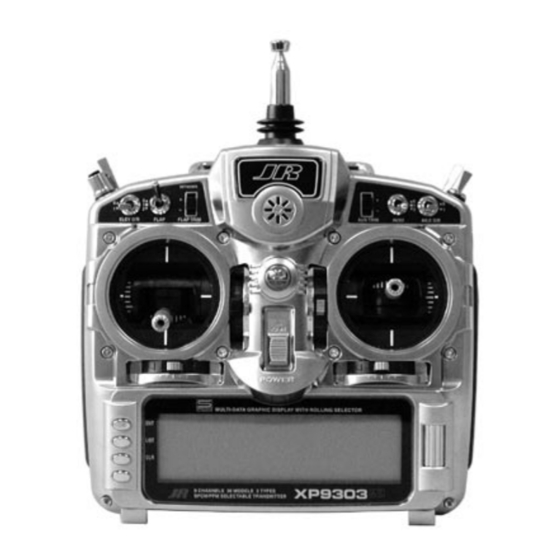
Page 9: Xp9303 Transmitter Features (Front
XP9303 Transmitter Features (Front) Mix Switch AUX2 Aileron Elevator AUX4/ Dual Rate Dual Rate Rudder Dual Aux Trim Gear Switch Rate Flap Trim Trainer Button Flap Switch Lever Lever Throttle/ Elevator/ Rudder Stick Aileron Stick Throttle Trim Elevator Trim Rudder Trim... -
Page 10: Xp9303 Transmitter Features (Rear
XP9303 Transmitter Features (Rear) Battery Cover CAUTION: THE BATTERY CONNECTION IS KEYED SO THAT IT CAN ONLY BE PLUGGED IN ONE DIRECTION. DO NOT FORCE... -
Page 11: Xp9303 Transmitter Features (Internal
XP9303 Transmitter Features (Internal) ELEVATOR TENSION SCREW RUDDER TENSION SCREW AILERON TENSION SCREW THROTTLE TENSION SCREW Control Stick Tension Adjustment Remove the six transmitter back screws as shown on the Adjust each screw for desired tension (counter-clockwise previous page. Remove the transmitter back, being careful to loosen stick feel;... -
Page 12: Advanced Digital Trims
Please also note that unlike conventional mechanical trim The XP9303’s Aileron, Elevator, Throttle and Rudder trim levers, when the XP9303 transmitter is in the off position, levers feature an audible center trim beep. This is helpful no changes can be made to the trim values during in determining the trim levers center position during transportation. -
Page 13: Direct Servo Control (Dsc)
Deluxe Switch Harness to use in the original setup of your aircraft while still – JRPA001, or a JR Chargeswitch – JRPA004, for the in the workshop. Because of the lower current draw on your transmitter, your working time at the bench will be DSC function to work.) Turn the switch harness to the... -
Page 14: Neckstrap Attachment
Neckstrap Attachment An eyelet is provided on the face of the XP9303 transmitter that allows you to connect a Neck Strap (JRPA023). This hook has been positioned so that your transmitter has the best possible balance when you use the neck strap. -
Page 15: Installation Requirements
4. Mount all switches away from the engine exhaust and correctly installed in your model. Here are a few away from any high vibration areas. Make sure the suggestions for installing your JR® equipment: switch operates freely and is able to operate over its full travel. -
Page 16: System Mode Glid Features
Sailplane- GLID Mode • Aileron-to-Rudder Mix–Features separate right and left mix values for each of the 5 available The GLID mode is intended for multi-function sailplanes. flight modes. The program software was developed by some of the • The Butterfly Menu–Provides 2 settings for flaps, world’s leading sailplane pilots and offers a level of flaperons and elevator values operated using the sophistication not found in any other sailplane system. -
Page 17: System Mode
System Mode System mode contains the foundational programming. To enter System Mode– System mode screens include model name, Press ENT and hold while turning on the transmitter. model reset, modulation, data transfer, etc.—functions that are typically set once and then are seldom The screen should appear as follows. -
Page 18: Model Select
Model Select Model select allows up to 30 different models to be stored 1. In the SYSTEM Menu, highlight and select Model and selected. SEL using the Selector. 2. Use the Selector to highlight and select the desired Note: When setting up a new model it is model number to be used. -
Page 19: Type Select
Type Select Type select allows the model type to be selected. Model 1. In the SYSTEM Menu, highlight and select Type SEL types include glider, acro or heli. Note: When changing using the Selector. model types the programming information will be reset to 2. -
Page 20: Modulation
2. Highlight and select either SPCM or PPM to match the the system will not function. receiver in the aircraft. Note: The XP9303 system is not designed for use with “Z” PCM receivers. [MODULAT.] MODEL 1... -
Page 21: Transfer A Model From The Xp9303 - (Transfer Function
Menu to obtain the Transfer display. SYSTEM Menu. Plug the other end of the trainer cord into another XP9303 transmitter while holding the ENT button down and prepare that transmitter for Receive as described below. -
Page 22: Transfer A Model To The Xp9303 - (Transfer Function
Press start on the transmitting XP9303 or 4. Select the model memory to receive the data by DataSafe unit to begin the data transfer to the XP9303. highlighting and selecting the model name/memory number and then scrolling to and selecting the model memory that is to receive the data. -
Page 23: Trim Step
Trim Step The Trim Step function provides for adjusting the When adjusting the analog spoiler trim, however, the sensitivity of the trim levers. It is useful during and after total trim travel is actually reduced when set to less than initial trimming of the aircraft, in order to trim the aircraft 100%. -
Page 24: Device Select
Device Select The device select screen is used to select the following: • To assign aux 2 channel to various levers, switches or sticks • To assign/activate flight modes to a variety • To assign aux 3 channel to various levers, of switches switches, buttons or sticks •... -
Page 25: Flight Modes
(es). The XP9303 offers up to 5 flight modes the cruise mode. A single flip of the switch neutralizes that include Launch, Land, Cruise, Speed and Thermal. -
Page 26: Activating And Assigning Flight Modes
Activating and Assigning Flight Modes In the factory default setting, all flight modes are inhibited. In system mode list rotate the Selector until Device Flight modes are activated and assigned to the desired SEL is highlighted. Press the Selector to access the switch position using the SPEED and LAUN functions in Device Select screen. -
Page 27: Activating And Assigning Flight Modes (Continued
Activating and Assigning Flight Modes (continued) To activate the speed thermal flight modes, highlight the cruise position. Try selecting the various flight SPEED and press the Selector to select the desired modes several times while looking at the main switch position. info screen and you’ll quickly become familiar with the switch priority. -
Page 28: Flap And Aux Functions
Flap and AUX Functions The Flap and Auxiliary functions can be assigned to Select the desired switch by highlighting it and press operate from several different switches, buttons or the the Selector. throttle stick. In device select, highlight the desired flap or aux function and press the Selector to access the available switches that can be programmed to operate each function. -
Page 29: Wing Type
Wing Type This screen allows the selection of V-tail, dual flap and, If your sailplane has a V-tail, activate the V-tail function by when dual flaps are activated, aileron-to-flap trim. highlighting INH and pressing the Selector. To access Wing type in System mode list, rotate the If your sailplane has dual flaps, activate the dual flap Selector to highlight Wing TYPE. -
Page 30: Function Mode
Function Mode Programs found in the function mode are more frequently To enter function modes, turn on the transmitter used. Not only are these functions used during initial then press the ENT button. To enter the function list setup, but many of these are commonly adjusted at the mode, press the list mode after the function mode field to change/optimize the flight characteristics and has been selected. -
Page 31: Function Mode (Continued
Function Mode (continued) Function mode contains the following screens: [D/R & EXP] 0 AUTO [DIFFEREN.] 110% CRUI:0 AILE FLAP AILE POS-0 110% CRUISE +60% +40% 125% LAUNCH +50% +30% POS-1 LAUN:1 125% LAND +20% LAND:2 125% POS-2 125% Dual Rate and Exponential Pg. S18 Differential Pg. - Page 32 Function Mode (continued) [PROG.Mix1] Point-0 SPOI ELEV Point-1 +_15 SW SELECT Point-2 Point-3 + 36 Point-4 Point-5 Point-6 + 44 1 OUT 0 1 2 3 4 5 6 Programmable Curve Mix Pg. S30 [TIMER] MODEL 1 TIMER 1:DOWN-T TIMER 2:STOP-W TIME SW TIM KEY INTEG-T...
- Page 33 D/R & EXP – DUAL RATE AND EXPONENTIAL Three dual and exponential rates are available and are 1. Highlight and select D/R & EXP in the FUNC.LIST selectable via flight modes or selected switches. Dual and to obtain the D/R & EXP display. If Flight Modes Expo rates are independently adjustable in each direction were activated earlier in the Devic.SEL function and by moving the appropriate stick in the desired direction.
-
Page 34: Rev.sw - Servo Reversing
REV.SW – SERVO REVERSING The servo reverse screen allow the direction of each servo 1. Highlight and select REV.SW in the FUNC.LIST to to be selected. obtain the servo reversing display. 2. Use the Selector to highlight and select those channels that need to be reversed. -
Page 35: Sub Trim
SUB TRIM Use Sub Trims to fine-tune the alignment of servo arms. 1. Highlight and select Sub Trim in the FUNC.LIST to obtain the Sub Trim Display. 2. Highlight and select the channels where the sub trims must be adjusted. Once a channel is selected, rotate the Selector until the servo arm is in the desired position. -
Page 36: Trvl. Adj - Travel Adjust
TRVL. ADJ - TRAVEL ADJUST Travel Adjust allows the independant adjustment of servo 1. Highlight and select TRVL ADJ. in the FUNC.LIST to travel for each direction of servo travel. obtain the Travel Adjust display. 2. Use the Selector to highlight and select each channel and adjust the travel in each direction by rotating the Selector. -
Page 37: Elevator-To-Flap Mix
Elevator-to-Flap Mix Elevator-to-flap mix is normally used to give several To access Elevator-to-flap mix, in Function Mode list, degrees of down flap when up elevator is applied. This rotate the Selector until ELE FLP M is highlighted. gives more pitch authority than would elevator alone, Press the Selector to access the Elevator-to-Flap mix and is commonly used for slope racers to improve high- menu. -
Page 38: Aileron-To-Flap Mix
Aileron-to-Flap Mix Aileron-to-flap mix causes the flaps to move in unison Note: Two aileron-to-flap mix values are with the ailerons. This function gives added roll response available—Pos0 and Pos1. Switches are available by mixing ailerons to flaps such that the entire trailing at the bottom of the screen that allow the selection edge functions as an aileron. -
Page 39: Camber Adjust
Camber Adjust The camber adjust screen allows a delay of up to 2 To access camber adjust, in FUNC.LIST rotate the seconds to be programmed to each of the 5 flight modes. Selector until CAMBR ADJ is highlighted. Press the This delay affects the flap, flaperon and elevator (and Selector to access the Camber Adjust menu. -
Page 40: Camber Mix
Camber Mix Important: Camber mix values are based on a To access camber mix, in FUNC.LIST rotate the percentage of the value programmed in Flap Rate Selector until CAMBR MIX is highlighted. Press the (see page S28). If no values are programmed in flap Selector to access the Camber Mix menu. -
Page 41: Aileron-To-Rudder Mix
Aileron-to-Rudder Mix Aileron-to-rudder mix causes the rudder to move in To access Aileron-to-Rudder mix, in FUNC.LIST rotate unison with ailerons. It is utilized to reduce adverse yaw the Selector until AIL RUD M is highlighted. Press and to improve the turning/ handling characteristics. the Selector to access the aileron-to-rudder mix menu. -
Page 42: Butterfly Mix (Landing Flaps
Butterfly Mix (Landing Flaps) The Butterfly Mix is the landing program that mixes the With this setting, the flap’s neutral position (trailing flaps, flaperons (ailerons as flaps) and elevator to the edge level) occurs when the spoiler stick is in the full up spoiler (throttle) stick. - Page 43 Flap Rate Flap Rate allows the independent up and down adjustment To access Flap Rate in FUNC.LIST rotate the Selector of flaps with the lever that camber mix is assigned to (flap until FLAP RATE is highlighted. Press the Selector lever or Aux.
-
Page 44: Motor Hold
Motor Hold Note: This function is only available when the motor To access Motor Hold in FUNC.LIST rotate the Selector is programmed to the spoiler stick in the device until MOTO. HOLD is highlighted. Press the Selector select menu. See Device Select Pg. S9. to access the Motor Hold menu.
Need help?
Do you have a question about the XP9303 and is the answer not in the manual?
Questions and answers