Table of Contents
Advertisement
Instruction
manual
To learn more about Porter-Cable
visit our website at:
http://www.porter-cable.com
Copyright © 2004 Porter-Cable Corporation
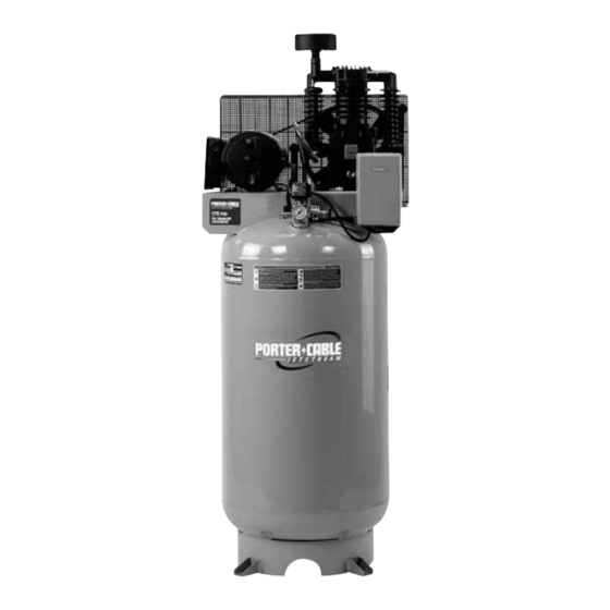
Oil Lube Two Stage
Air Compressor
Please make certain that the person who is
to use this equipment carefully reads and
understands these instructions before
starting operations.
The Model and Serial No. plate is located on the frame.
Record these numbers in the spaces below and retain for
future reference.
®
Model No.
Type
Serial No.
ESPAÑOL: PÁGINA 27
FRANÇAIS: PAGE 53
CPLMC7580V2C
IMPORTANT
Part No. D24225-049-2
Advertisement
Table of Contents

Related Manuals for Porter-Cable CPLMC7580V2C


Summary of Contents for Porter-Cable CPLMC7580V2C
-
Page 1: Instruction Manual
Oil Lube Two Stage Air Compressor CPLMC7580V2C IMPORTANT Please make certain that the person who is To learn more about Porter-Cable to use this equipment carefully reads and visit our website at: understands these instructions before http://www.porter-cable.com starting operations. -
Page 2: Safety Guidelines - Definitions
This tool was designed for certain applications. Porter-Cable strongly recommends that this tool NOT be modified and/or used for any application other than for which it was designed. If you have any questions relative to its application DO NOT use the tool until you have written Porter-Cable and we have advised you. -
Page 3: Risk Of Explosion Or Fire
IMPORTANT SAFETY INSTRUCTIONS SAVE THESE INSTRUCTIONS IMPROPER OPERATION OR MAINTENANCE OF THIS PRODUCT COULD RESULT IN SERIOUS INJURY AND PROPERTY DAMAGE. READ AND UNDERSTAND ALL WARNINGS AND OPERATING INSTRUCTIONS BEFORE USING THIS EQUIPMENT. HAZARD RISK OF EXPLOSION OR FIRE WHAT CAN HAPPEN HOW TO PREVENT IT ALWAYS OPERATE THE COMPRESSOR IN A IT IS NORMAL FOR ELECTRICAL CONTACTS... -
Page 4: Risk Of Bursting
HAZARD RISK OF BURSTING AIR TANK: THE FOLLOWING CONDITIONS COULD LEAD TO A WEAKENING OF THE TANK, AND RESULT IN A VIOLENT TANK EXPLOSION AND COULD CAUSE PROPERTY DAMAGE OR SERIOUS INJURY. WHAT CAN HAPPEN HOW TO PREVENT IT FAILURE TO PROPERLY DRAIN DRAIN TANK DAILY OR AFTER EACH USE. -
Page 5: Risk Of Electrical Shock
HAZARD RISK OF ELECTRICAL SHOCK WHAT CAN HAPPEN HOW TO PREVENT IT NEVER OPERATE COMPRESSOR YOUR AIR COMPRESSOR IS POWERED BY OUTDOORS WHEN IT IS RAINING OR IN WET ELECTRICITY. LIKE OTHER CONDITIONS. ELECTRICALLY POWERED DEVICE, IF IT IS NOT USED PROPERLY IT MAY CAUSE NEVER OPERATE COMPRESSOR... -
Page 6: Risk Of Burns
HAZARD RISK OF BURNS WHAT CAN HAPPEN HOW TO PREVENT IT TOUCHING EXPOSED METAL SUCH AS THE NEVER TOUCH ANY EXPOSED METAL PARTS COMPRESSOR HEAD OR OUTLET TUBES, ON COMPRESSOR DURING OR IMMEDIATELY AFTER OPERATION. COMPRESSOR WILL CAN RESULT IN SERIOUS BURNS. REMAIN HOT FOR SEVERAL MINUTES AFTER OPERATION. -
Page 7: Specifications
SPECIFICATIONS Model No. CPLMC7580V2C Horsepower Voltage/Hertz/Phase 240/60/1 Minimum Branch Circuit Requirement 30 Amp *Fuse Type Time Delay Air Tank Capacity (Gallon) 80 ASME, Vertical Approximate Cut-in Pressure 145 PSIG Approximate Cut-out Pressure 175 PSIG SCFM @ 175 PSIG 23.5 Magnetic Starter Included * A circuit breaker is preferred. -
Page 8: Tools Required For Assembly
ASSEMBLY Tools Required for Assembly 1 - 9/16" socket or open end wrench 1 - electric drill Unpacking Remove all packaging. It may be necessary to brace or support one side of the outfit when removing the pallet because the air compressor will have a tendency to tip. -
Page 9: Location Of The Air Compressor
To Install Air Filter Attach elbow to pump using bolts provided. Tighten until snug. Insert threaded end of air filter assembly into elbow and tighten until snug. INSTALLATION HOW TO SET UP YOUR UNIT Location of the Air Compressor • Locate the air compressor in a clean, dry, and well ventilated area. -
Page 10: Wiring Instructions
Place the (4) washers (supplied) between the floor and air compressor feet. If needed, solid shims may be placed between the washers and floor to evenly distribute weight on all four feet. See next figure. Place the (4) 3/8" lag screws through the air compressor feet, washers, shims, and into the anchors. -
Page 11: Air Distribution System
● Use pipe that is the same size as the air tank outlet. Piping that is too small will restrict the flow of air. ● If piping is over 100 feet long, use the next larger size. ● Bury underground lines below the frost line and avoid pockets where condensation can gather and freeze. -
Page 12: Know Your Air Compressor
OPERATION Know Your Air Compressor READ THIS OWNER’S MANUAL AND SAFETY RULES BEFORE OPERATING YOUR UNIT. Compare the illustrations with your unit to familiarize yourself with the location of various controls and adjustments. Save this manual for future reference. Description of Operation Become familiar with these controls before operating the unit. -
Page 13: Before Starting Break-In Procedure
Check Valve: When the air compressor is operating, Check Valve the check valve is "open", allowing compressed air to enter the air tank. When the air compressor reaches "cut-out" pressure, the check valve "closes", allowing air pressure to remain inside the air tank. Pressure Release Valve: The pressure release valve, located on the side of the pressure switch, is designed to automatically release compressed air... -
Page 14: Before Each Start-Up
Check for excessive vibration. Readjust or shim air compressor feet, if necessary. After 20 minutes, close the globe valve.The air receiver will fill to "cut-out" pressure and the motor will stop. Before Each Start-Up: Place On/Auto/Off lever to "OFF". Close the globe valve. Attach hose and accessories. -
Page 15: Customer Responsibilities
MAINTENANCE Customer Responsibilities Before Every Every Every Every Every each Yearly hours hours hours hours hours ● Check Safety Valve ● Drain Tank ● Check Oil ● ● Change Oil Unusual Noise and/or ● Vibration ● Air Filter Drive Belt-Condition ●... -
Page 16: To Drain Tank
To Drain Tank NOTE: Operation of the air compressor will cause condensation to build up in the air tank. Always drain tank on a washable surface or in a suitable container to prevent damaging or staining surfaces. Set the On/Auto/Off lever to "OFF". Close the globe valve. -
Page 17: Belt Replacement
Air Filter - Inspection and Replacement Hot surfaces. Risk of burn. Compressor heads are exposed when filter cover is removed. Allow compressor to cool prior to servicing. A dirty air filter will not allow the compressor to operate at full capacity. Keep the air filter clean at all times. -
Page 18: Air Compressor Pump Intake And Exhaust Valves
Motor Pulley/Flywheel Alignment NOTE: Once the motor pulley has been moved from its factory set location, the grooves of the flywheel and pulley must be aligned to within 1/16" to prevent excessive belt wear. The air compressor flywheel and motor pulley must be in-line (in the same plane) within 1/16"... -
Page 19: Service And Adjustments
SERVICE AND ADJUSTMENTS Unit cycles automatically when power is on. When doing Maintenance, you may be exposed to voltage sources, compressed air or moving parts. Personal injuries can occur. Before performing any Maintenance or repair, unplug the compressor and bleed off all air pressure. -
Page 20: Additional Service
Using a screwdriver, carefully push the valve disc up and down. NOTE: The valve disc should move freely up and down on a spring which holds the valve disc in the closed position, if not the check valve needs to be cleaned or replaced. - Page 21 STORAGE Before you store the air compressor, make sure you do the following: Review the "Maintenance" section on the preceding pages and perform scheduled maintenance as necessary. Set the On/Auto/Off lever to "OFF". Close the globe valve. Remove the air tool or accessory. Open the globe valve and allow the air to slowly bleed from the air tank until tank pressure is approximately 20 psi.
-
Page 22: Troubleshooting
TROUBLESHOOTING Performing repairs may expose voltage sources, moving parts or compressed air sources, moving parts or compressd air sources. Personal injury may occur. Prior to attempting any repairs, unplug the air compressor and bleed off all air tank air pressure. CORRECTION CAUSE PROBLEM... - Page 23 CORRECTION CAUSE PROBLEM If there is an excessive amount It is normal for "some" Pressure reading of pressure drop when the pressure drop to occur. on the regulated accessory is used, adjust the pressure gauge regulator as instructed in the (if equipped) Operation section.
- Page 24 CORRECTION CAUSE PROBLEM Motor will not Let motor cool off and Motor overload protection overload switch will run. switch has tripped. automatically reset. Motor will start automatically Tank pressure exceeds when tank pressure drops pressure switch "cut-in" below "cut-in" pressure of pressure.
- Page 25 CORRECTION CAUSE PROBLEM Knocking Noise. Possible defect in safety Operate safety valve manually valve. by pulling on ring. If valve still leaks, it should be replaced. Defective check valve. Remove and clean, or replace. Loose pulley. Tighten pulley set screw, 145-165 in.-lbs.
-
Page 26: Limited Warranty
90 Day – Service parts Engine warranties are the responsibility of the engine manufacturer. Warranties of merchandise sold by Porter-Cable which has been manufactured by and identified as the product of another company are the responsibility of the manufacturer of that product.
Need help?
Do you have a question about the CPLMC7580V2C and is the answer not in the manual?
Questions and answers