Table of Contents
Advertisement
Quick Links
Instruction Manual
High Voltage Power Supply
SPELLMAN
HIGH VOLTAGE ELECTRONICS
CORPORATION
475 Wireless Blvd.
Hauppauge, New York, 11788
+1(631) 630-3000*FAX: +1(631) 435-1620*
E-mail:
sales@spellmanhv.com
Website: www.spellmanhv.com
SL150 SERIES MANUAL
SL150kV
MODEL :
SERIAL# :
DATE :
R
118092-001 Rev A
Advertisement
Table of Contents

Related Manuals for Spellman SL150kV


Summary of Contents for Spellman SL150kV
- Page 1 Instruction Manual SL150kV High Voltage Power Supply MODEL : SERIAL# : DATE : SPELLMAN HIGH VOLTAGE ELECTRONICS CORPORATION 475 Wireless Blvd. Hauppauge, New York, 11788 +1(631) 630-3000*FAX: +1(631) 435-1620* E-mail: sales@spellmanhv.com Website: www.spellmanhv.com 118092-001 Rev A SL150 SERIES MANUAL...
-
Page 2: Power Supply
100ppm/hr after a 2 hour warm up, for both voltage and current regulation Corporate Headquarters For locations worldwide www.spellmanhv.com Hauppauge, New York USA 128062-001 REV. F +1-631-630-3000 FAX: +1-631-435-1620 e-mail: sales@spellmanhv.com Spellman High Voltage is an ISO 9001:2008 and ISO 14001:2004 registered company... - Page 3 P = positive output polarity, 1200 = maximum output power (watts), BFP = Blank Front Panel, LL(20) = 20 foot HV cable. Corporate Headquarters For locations worldwide www.spellmanhv.com Hauppauge, New York USA 128062-001 REV. F +1-631-630-3000 FAX: +1-631-435-1620 e-mail: sales@spellmanhv.com Spellman High Voltage is an ISO 9001:2008 and ISO 14001:2004 registered company...
-
Page 4: Important Safety Precautions
CAUTION notes in the text indicate procedures to be followed to avoid possible damage to equipment. Copyright © 2000, Spellman High Voltage Electronics Corporation. All Rights Reserved. This information contained in this publication is derived in part from proprietary and patent data. This information has... -
Page 5: Table Of Contents
Table of Contents PAGE 1. INTRODUCTION Description of the SL150 ..................1 Standard Features....................2 1.2.1 Remote Operating Features ..............2 1.2.2 System Status and Fault Diagnostic Display ........2 Options.........................3 Interpreting the Model Number ................4 2. INSPECTION & INSTALLATION Initial Inspection ....................5 Mechanical Installation..................5 3. -
Page 6: List Of Figures
6. MAINTENANCE Periodic Servicing....................23 Performance Test ....................23 High Voltage Dividers ..................23 7. REPLACEMENT PARTS Replacement Parts....................24 Correspondence and Ordering Spare Parts ............24 8. FACTORY SERVICE 8.1 Warranty Repairs ....................25 8.2 Factory Service Procedures .................25 8.3 Ordering Options and Modifications ..............25 8.4 Shipping Instructions ...................25 LIST OF FIGURES Figure 2.1... -
Page 7: Introduction
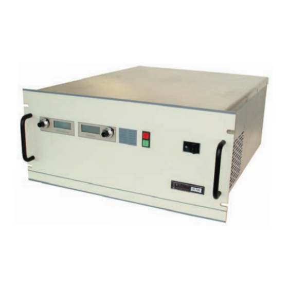
Chapter 1 NTRODUCTION 1.1 Description of the SL150 he SL150 voltage power supply provides very well regulated, low ripple high voltage in a highly efficient, compact design. The improvements in size and performance over traditionally designed high voltage power supplies are due to the resonant topology and unique control circuitry of the SL design. -
Page 8: Standard Features
1.2 Standard Features REMOTE HIGH VOLTAGE CONTROL: The SL150 incorporates several standard features Allows remote control of HIGH VOLTAGE ON and designed to optimize user satisfaction and safety. HIGH VOLTAGE OFF. Signals are also provided SLOW START: This feature provides a gradual for remote indication of HV ON or HV OFF status. -
Page 9: Options
Remote Fault Reset power supply at the factory in a short time. For price and retrofit arrangements, contact the Spellman Sales Table 1.1 SL150 Options Department. Note: APT/CPC cannot be combined with EFR... -
Page 10: Interpreting The Model Number
1.4 Interpreting the Model Number The model number of the power supply describes its capabilities. After the series name is: 1. the maximum voltage (in kV). 2. the polarity of the unit: positive (P), negative (N) or reversible (PN). 3. the maximum output (in watts). 4. -
Page 11: Inspection & Installation
Inspect the package exterior for evidence of damage due 2.2 Mechanical Installation to handling in transit. Notify the carrier and Spellman immediately if damage is evident. Do not destroy or Units in the SL Series have front panel holes for standard remove any of the packing material used in a damaged EIA rack mounting. -
Page 12: Figure 2.1 Sl150 Dimensions
I/O INTERFACE LINE INPUT REAR VIEW Figure 2.1 SL150 Dimensions SL150 MANUAL 118093-001 REV B... -
Page 13: Operating Instructions
Chapter 3 PERATING NSTRUCTIONS E) Plug the high-voltage output cable provided with the 3.1 Operation unit into the rear of the supply and hand tighten the knurled collar. WARNING F) OPTIONS NOTE: See Section 5 for hook-up and operating instructions for the options on your unit. THIS EQUIPMENT GENERATES DANGEROUS Custom models may also require set-up changes. -
Page 14: Standard Features
HIGH VOLTAGE OFF switch. In the HIGH Spellman application engineers are available to assist in VOLTAGE OFF mode the power supply’s fault and interface circuitry design. All interface cables should be interface circuits are still active. - Page 15 the interlock terminals, the unit’s high voltage REMOTE MONITOR: Test points are made inverter will be disabled. During high voltage available at the terminal block on the rear of the operation, revert to the HIGH VOLTAGE OFF chassis for monitoring the voltage and current output. mode.
-
Page 16: Figure 3.1 Sl150 Typical Operating Set Up
I/O INTERFACE LINE INPUT Figure 3.1 Typical Operating Setup SL150 MANUAL 118093-001 REV B... -
Page 17: Table 3.1 Rear Panel Interface 25 Pin Mini D
SIGNAL SIGNAL PARAMETERS Power Supply Common Signal Ground External Inhibit Ground = Inhibit, Open = HV ON External Interlock +15V at Open, <15mA at Closed External Interlock Return Return For Interlock Current Monitor 0 to 10V = 0 to 100% Rated Output kV Test Point 0 to 10V = 0 to 100% Rated Output +10V Reference... -
Page 18: Figure 3.2A Wiring Diagram For Remote Programming Via Voltage Source
Voltage Source 0-10V = 0-100% of Rated Output PS Common It is recommended that analog signals be isolated via isolation amplifiers. All cables should be shielded with the shield being returned to the chassis ground of the High Voltage Power Supply. Remote Current Program... -
Page 19: Figure 3.3 Remote Monitor Test Point Designations
PS Common It is recommended that analog signals be isolated via isolation amplifiers. All cables should be shielded Current with the shield being returned to the chassis ground Monitor of the high voltage power supply. Voltage Monitor Z out = 4.99k ohms ±0.1% Z out = 4.99k ohms ±0.1% Figure 3.3 -- Remote Monitor Test Point Designations It is recommended to use relay contacts for... -
Page 20: Figure 3.5 External Inhibit Interface Circuit
The transistor should be located as close as possible to the power supply All cables should be shielded with the shields being returned to the chassis ground of the High Voltage Power Supply. +15V PS Common Transistor Inhibits High Voltage 2.2k High Voltage Power Supply Internal inhibit circuitry. -
Page 21: Figure 3.7 Remote High Voltage On And Remote High Voltage Off Indicator Circuit
12Vdc lamps or relay coils may replace opto-couplers. Opto-couplers, lamps or relays should be located as close as possible to the high voltage power supply. All cables should be shielded with the shields being returned to the chassis ground of the High Voltage Power Supply. PS Common General Purpose Opto-Coupler... -
Page 22: Figure 3.8 Remote Indicators Interface
Voltage Control Indicator R limit Current Control 10mA max. Indicator R limit Power Control 10mA max. Indicator R limit 10mA max. R Limit must be > 1kW R1-R3=680W 1/4W Figure 3.8 -- Remote Mode Indicators Interface SL150 MANUAL 118093-001 REV B... -
Page 23: Principles Of Operation
SL power supply. For details on a specific circuit, operate the power supply unless the user has a consult Spellman’s Engineering Department. sufficient knowledge of the dangers and hazards of working with high voltage. Do not attempt to ... -
Page 24: High Voltage Transformer
SL150, details of actual circuits used may K2 provides switching between feedback and program differ slightly from the above descriptions. Consult signal for the front panel DVM’s. This allows the user to Spellman’s Engineering Department questions preset the desired output before energizing high voltage. -
Page 25: Options
Chapter 5 PTIONS he options available for this power supply are 5.5 Extra Length Output described in this section. Interface diagrams are Cable--LL(ft) shown where required. Options are specified by including the option code in the model number as Standard output cable is 10 feet of shielded high voltage described in Section 1.5. -
Page 26: External Fault Relay Option
With the installation of the EFR option, if any of these faults occur, a relay will be activated to provide a remote Spellman welcomes the opportunity to customize units to indication that the power supply has reverted to the fit your requirements or to develop new products for your “power down”... -
Page 27: Figure 5.1 Adjustable Power Remote Interface Control
Remote Remote Remove internal Power Power jumper, JP1 ON Monitor Program Control/Pwr PWB 0-10V for remote =0-100% Programing. (Jumper power connects internal, output Zout= pot, factory set at 20K ohm 4.99k ohm 0.1% 103% of max power). min. Remote Power Programming Z in = 10M ohm potentiometer... -
Page 28: Sl150 Manual 118093-001 Rev B
DETAIL A RS232 FILAMENT OUTPUT I/O INTERFACE LINE INPUT REAR VIEW VIEW B-B DETAIL A Figure 5.2 Reverse Polarity Option SL150 MANUAL 118093-001 REV B... -
Page 29: Maintenance
Use compressed air to blow dust and a high voltage divider such as the Spellman HVD- out of the inside of the unit. Avoid touching or handling 200 is needed for performance tests. All test components the high voltage assembly. -
Page 30: Replacement Parts
7.1 Replacement Parts 7.2 Correspondence and Ordering Spare Parts Contact the Spellman Customer Service Department for parts lists for specific models. Each power supply has an identification label on the rear of the chassis that bears its model and serial number. -
Page 31: Factory Service
The Warranty is void if the unit is worked into Spellman’s power supplies by our factory. For prices on by other than Spellman personnel. See the Warranty in and arrangements, contact the Spellman Sales Department. the rear of this manual for more information. Follow the return procedures described in Section 8.2. -
Page 32: Wichtige Sicherheitshinweise
WICHTIGE SICHERHEITSHINWEISE SICHERHEIT DIESES HOCHSPANNUNGSNETZTEIL ERZEUGT LEBENSGEFÄHRLICHE HOCHSPANNUNG. SEIN SIE SEHR VORSICHTIG BEI DER ARBEIT MIT DIESEM GERÄT. Das Hochspannungsnetzteil muß immer geerdet sein. Berühren Sie die Stecker des Netzteiles nur, wenn das Gerät ausgeschaltet ist und die elektrischen Kapazitäten des Netzteiles und der angeschlossenen Last entladen sind. Die internen Kapazitäten des Hochspannungsnetzteiles benötigen ca. - Page 33 PRECAUTIONS IMPORTANTES POUR VOTRE SECURITE CONSIGNES DE SÉCURITÉ ETTE ALIMENTATION GÉNÈRE DES TENSIONS QUI SONT DANGEUREUSES ET PEUVENT ÊTRE FATALES OYEZ EXTRÊMENT VIGILANTS LORSQUE VOUS UTILISEZ CET ÉQUIPEMENT Les alimentations haute tension doivent toujours être mises à la masse. Ne touchez pas les connectiques sans que l’équipement soit éteint et que la capacité à la fois de la charge et de l’alimentation soient déchargées.
- Page 34 IMPORTANTI PRECAUZIONI DI SICUREZZA SICUREZZA QUESTO ALIMENTATORE GENERA TENSIONI CHE SONO PERICOLOSE E POTREBBERO ESSERE MORTALI. PONI ESTREMA CAUTELA QUANDO OPERI CON QUESO APPARECCHIO. Gli alimentatori ad alta tensione devono sempre essere collegati ad un impianto di terra. Non toccare le connessioni a meno che l’apparecchio sia stato spento e la capacità interna del carico e dell’alimentatore stesso siano scariche.
- Page 35 The buyer’s sole remedy for a claimed breach of this warranty, and Spellman’s sole liability is limited, at Spellman’s discretion, to a refund of the purchase price or the repair or replacement of the power supply at Spellman’s cost. The buyer will be responsible for shipping charges to and from Spellman’s plant. The buyer will not be entitled to make claim for, or recover, any anticipatory profits, or incidental, special or consequential damages resulting from, or in any way relating to, an alleged breach of this warranty.
Need help?
Do you have a question about the SL150kV and is the answer not in the manual?
Questions and answers