Table of Contents
Advertisement
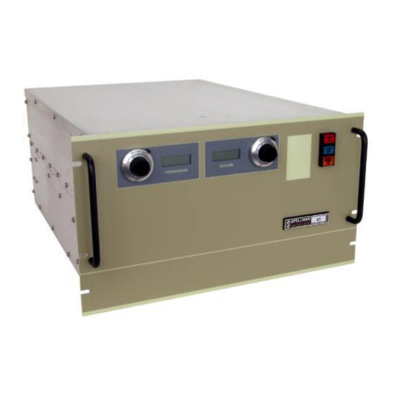
Instruction Manual
ST/STA/STR SERIES
High Voltage Power Supply
SPELLMAN
HIGH VOLTAGE ELECTRONICS
CORPORATION
475 Wireless Blvd.
Hauppauge, New York, 11788
+1(631) 630-3000*FAX: +1(631) 435-1620*
E-mail:
sales@spellmanhv.com
Website: www.spellmanhv.com
ST/STA/STR SERIES MANUAL
MODEL :
SERIAL# :
DATE :
R
118108-001 Rev C
Advertisement
Chapters
Table of Contents


Need help?
Do you have a question about the ST SERIES and is the answer not in the manual?
Questions and answers