
Related Manuals for Chaffoteaux & Maury Mira system FF


Summary of Contents for Chaffoteaux & Maury Mira system FF
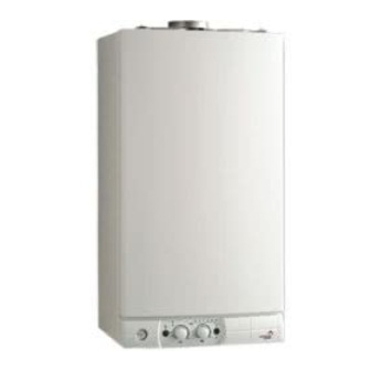
- Page 1 COMBINATION BOILER Heating only (system) Heating + sanitary hot water together (system plus) Fanned Flue System Installation and Operating Manual MODE AUTO TEMP...
-
Page 2: Table Of Contents
Contents Installer’s instruction Page 1 - description......................2 - dimensions ......................3 - water specifications ..................... 4 - installation requirements ..................5 - air intake and burnt gas outlet connections............6 - fitting the boiler....................7 - electrical connections..................8 - starting up ......................9 - fitting the casing .................... -
Page 3: Description
INSTALLER’S INSTRUCTION 1. Description 1.- sheet steel frame with expansion vessel 2.- sealed casing 3.- hood with extractor fan 4.- copper main heat exchanger 5.- combustion chamber 6.- multigas burner comprising: • a removable injector manifold • an ignition electrode •... -
Page 4: Dimensions
2. Dimensions Measurements in mm Safety valve outlet Heating flow and tank Tank backflow (system plus) Gas inlet Cold water supply Heating backflow Weight with packaging: 24 kW: 32 kg 30 kW: 33 kg 172,5 121,5 J K L M N 450 min. -
Page 5: Installation Requirements
4. Installation requirements 4.1 REGULATIONS 4.2 BOILER LOCATION - the centre line of the external flue duct must be placed at a PRIVATE HOMES distance of at least 0.40 m from any opening window and STATUTORY REQUIREMENTS FOR INSTALLATION AND a distance of at least 0.60 m from any ventilation hole MAINTENANCE (depending on the type of outlet chosen, refer to the flue... -
Page 6: Air Intake And Burnt Gas Outlet Connections
Connecting gas intake and exhaust ducts The boiler should only be installed with a fresh air inlet and smoke outlet device supplied by the boiler manufacturer. The kits are supplied separately from the boiler to meet the requirements of various types of installation. For more information about inlet/outlet accessories, refer to the accessories catalogue and the installation instructions inside the kits. - Page 7 In the special case where the connection is with separate tubes and with the boiler installed at a minimum distance of 6 cm from the wall, make a 10 cm ø hole, thus enabling better assembly between the fresh air elbow and the tube outside the wall (see diagram).
-
Page 8: Fitting The Boiler
6. Fitting the boiler - place the paper installation jig in the selected position on the wall - fit the hanging bracket - bring the water pipes and the electrical connection to the locations shown on the fitting template - remove the 2 locking screws A which secure the front panel (fig. 7) - remove the front panel - offer the boiler up to its bracket and allow it to drop into position while pressing on it (fig. -
Page 9: Electrical Connections
7. Electrical connections Regulations: - in accordance with the regulations, an all-pole iso- lating device with a contact opening gap of at least 3 mm must be installed in the boiler's stationary power supply installation - the boiler must be connected to a fixed junction box using the cable supplied Location of connections: - the 230 V supply lead and room thermostat inputs... -
Page 10: Starting Up
8. Operating PRESSURISATION (fig. 12) Heating circuit and tank: - open cold water tap 34 - check that the heating flow 31, heating backflow 35 and tank backflow 32 taps (compy system plus) are open - open filling tap 36 - close the tap again when the needle of pressure gauge 19 (fig. -
Page 11: Factory Settings
8. Operating (continued) Célectic Tempo Débistat Sanitaire 1,5 sec Tempo Débistat Sanitaire 0 sec TIC 3 min. TIC 30 sec. Post-circulation 30 s Post-circulation 3 min. Post circulation 30 s Post circulation 3 mn Modulating Operation Fonctionnement Modulant ON/OFF operation Fonctionnement TOUT OU RIEN Heating setting to 40 °C Consigne chauffage à... -
Page 12: Fitting The Casing
9. Fitting the casing Fitting the casing Remove the protective film on the casing: - offer the casing up (fig. 14) - engage hooks N in notches R operation 1 - fit the top of the panel in place - close the panel mounting clamps (fig. 15) N.B. -
Page 13: Gas Conversion
10. Gas conversion When changing to a gas different from the one for which the boiler is equipped, you should replace the parts supplied with the conversion kit and adjust the gas valve in accordance with the method described below. Adjusting the nominal output •... -
Page 14: Fault Codes
11. Fault codes - Information If the equipment has an operating fault, one or more LEDs (23) flash according to the type of fault listed in the table below. CODE FAULT INFORMATION 30 40 50 60 70 80 H H H H H H H H H H G G Locked - overheating. -
Page 15: Points To Note
12. Particular characteristics By-pass valve assembly direction... -
Page 16: Controls
INSTRUCTIONS FOR THE USER 13. Controls (system plus) Fig.20 Control panel (fig. 20) Taps and valves (fig. 21) 31. Central heating flow isolating valve and tank 19. - heating circuit pressure gauge 32. Tank backflow (system plus) 20. - ON/OFF push button and ON indicator light 21.- domestic hot water function ON and hot water 33: Gas tap 34: Cold water supply tap... -
Page 17: Operation
14. Operation Starting up 1. check that the appliance's general gas shut-off tap is open and that the boiler is supplied with power. 2. check that there is sufficient pressure in the heating circuit: pressure gauge needle at least 1.2 bar with 1.7 bar at max. cold 3. -
Page 18: Maintenance
15. Maintenance Current legislation requires a mandatory annual service of your water heater. Once a year, have it checked by a qualified professional. Annual service contract formats may be suggested to you by service providers for all boiler servicing. Contact your gas fitter or our commercial services. -
Page 19: Operating Faults
19. Operating faults Fault Cause Solution Control gas, water and electrical The boiler doesn’t start No gas, no water or no electricity supply, fuses… Air in the gas pipe Follow procedure in chapter 8 Room thermostat switched off Set up the room thermostat Wait for a few minutes Press on reset button 25 (fig.20) the red led turn off and the boiler attempts to re-... -
Page 20: Technical Specifications
20. Technical specifications Model 24 kW FF 30 kW FF 10 to 24 kW 12 to 30 kW Heating power 24 kW 30 kW Variable tank pre-heating power Pn max Category II 2E+3+ Fresh air flow rate required for combustion 43 m 54 m Associated BACD tank capacity...
Need help?
Do you have a question about the Mira system FF and is the answer not in the manual?
Questions and answers