Advertisement
Quick Links
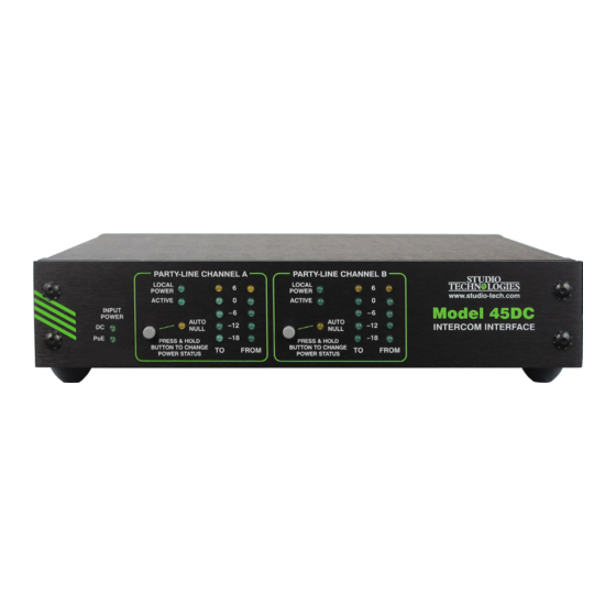
Model 45DC
Dante to Dual Party-Line
Intercom Interface
User Guide
Issue 4, June 2020
This User Guide is applicable for serial numbers
M45DC-00151 and later with application firmware 3.1 and later
and Dante firmware 4.6.0 (UltimoX2 4.2.2.3) and later
Copyright © 2020 by Studio Technologies, Inc., all rights reserved
studio-tech.com
50017-0620, Issue 4
Advertisement

Subscribe to Our Youtube Channel
Related Manuals for Studio Technologies 45DC


Summary of Contents for Studio Technologies 45DC
- Page 1 Issue 4, June 2020 This User Guide is applicable for serial numbers M45DC-00151 and later with application firmware 3.1 and later and Dante firmware 4.6.0 (UltimoX2 4.2.2.3) and later Copyright © 2020 by Studio Technologies, Inc., all rights reserved studio-tech.com 50017-0620, Issue 4...
- Page 2 This page intentionally left blank.
-
Page 3: Table Of Contents
Table of Contents Revision History ............4 Introduction ..............5 Installation ..............9 Configuration ..............12 Operation ..............15 Technical Notes ............. 20 Specifications ..............25 Model 45DC User Guide Issue 4, June 2020 Studio Technologies, Inc. Page 3... -
Page 4: Revision History
1. Documents enhanced unit identification feature (added to application firmware version 2.5). 2. Adds improvements to IP address configuration assignment explanation. Issue 1, January 2015: 1. Initial release. Issue 4, June 2020 Model 45DC User Guide Page 4 Studio Technologies, Inc. -
Page 5: Introduction
An Ethernet connection is all that’s ty-line (PL) intercom technology. The unit required to make the Model 45DC part of a provides two independent single-channel sophisticated, networked audio system. interfaces that each support one party-line A Model 45DC can interconnect with devic- audio channel. - Page 6 Model 45DC Interfaces. At each end during setup and operation. Support for a Model 45DC is connected to one or two transporting call light signals between Mod- party-line circuits as well as the Dante el 45DC units is also provided.
- Page 7 Model 45DC using the Dante Controller software application. This makes selecting The Model 45DC’s audio circuitry was the way in which a Model 45DC fits into a designed in the spirit of professional specific application a simple matter. audio equipment rather than that found in typical party-line intercom gear.
- Page 8 20 kHz audio tone, and PoE power source. and transport the tone over the Dante audio path. A Model 45DC unit at the “far Simple Installation end” will detect the tone and re-generate The Model 45DC uses standard con-...
-
Page 9: Installation
System Components using two 3-pin male XLR connectors. The Model 45DC is housed in a rugged yet Included in the shipping carton are the lightweight aluminum enclosure that is de- Model 45DC Intercom Interface and a user signed to be “field tough.” It can be used guide. - Page 10 Once the desired one or two Model 45DC To attach a Model 45DC unit to the single- units have been installed in a rack-mount unit rack-mount panel, begin the process front panel, the assembly can be mounted by using a 5/64-inch hex wrench to remove into the designated equipment rack.
- Page 11 1, 22 to 30 12 volts, correct operation will take place volts DC is on pin 2, and audio is on pin 3. over a 10 to 18 volt range. The Model 45DC An impedance-generating network pro- requires 1.0 amperes maximum for cor- vides a 200 ohm audio load from pin 3 to rect operation.
-
Page 12: Configuration
Dante audio 2-channel circuits and devices is to use the connections. Studio Technologies Model 45DR Interface. This unit, the “cousin” of the Model 45DC, is optimized for 2-channel party-line inter- com applications. Rather than providing two single-channel interfaces the Model 45DR provides one 2-channel interface. - Page 13 SW2 is in its on (up) position no minimum take place. party-line current draw is required for the When the Model 45DC has been set to active LED to be lit and an output audio not provide local power the party-line path to be active.
- Page 14 Model 45DC’s selected using the Dante Controller appli- circuitry. The Model 45DC uses the Ultimo cation. The Model 45DC can serve as the 2-input/2-output integrated circuit to imple- clock master for a Dante network but in ment the Dante architecture.
-
Page 15: Operation
It will slowly light on and off green SYS, SYNC, and PoE LEDs (all located on when the Model 45DC is part of a Dante the back panel below the etherCON con- network and is serving as a clock master. - Page 16 –14 dBu is being sent to the associated offers an identify command that can be party-line intercom circuit. (Also note that used to help locate a specific Model 45DC. this –14 dBu signal on the party-line in- When identify is selected for a specific unit tercom circuit will translate to a –20 dBFS...
- Page 17 –20 dBFS on the as- sociated Dante channels. This should lead Two green LEDs are located on the front to the best performance of the Model 45DC panel and are associated with operating and associated party-line user devices.
- Page 18 Power is again applied to pin 2, the be connected to a Model 45DC. A newer active LED will light, and monitoring won’t version, the RS-701 has a quiescent cur- begin for another three seconds.
- Page 19 Model indicate this condition. Only one auto null 45DC operation will be able to take place. process can be active at any one time. Nothing will happen if either auto null but-...
-
Page 20: Technical Notes
Muting the microphones can be significant This DC voltage is summed (added) to as obtaining a “deep” null requires that any audio that is present. The Model 45DC no extraneous signals be present on the detects when a call light signal is active by intercom circuit. - Page 21 48 kHz sample rate can easily transport a Common Ground 20 kHz signal. When the Model 45DC detects DC on the The Model 45DC provides two audio path (pin 3 of the back-panel inter- independent single-channel party-line face connector) it will digitally generate intercom interfaces.
- Page 22 “mini” LAN with a address will be assigned using the link- personal computer connected directly to local protocol. This protocol is known the Model 45DC. Then by using the appro- in the Microsoft world as Automat- ®...
- Page 23 While the firmware file inside of the zip .1 O file will adhere to the naming convention required by the Model 45DC, the name of the zip file itself will include the file’s ver- sion number. For example, a file named m45DCv2r2MCU.zip would indicate that...
- Page 24 10 seconds, the Model 45DC will restart using the newly- loaded application firmware. 7. At this time the Model 45DC is function- ing with the newly-loaded application firmware and the USB flash drive can be removed. But to be conservative, remove power first and then remove the USB flash drive.
-
Page 25: Specifications
0.2 pounds (0.09 kg) Power Source, Pin 2: 28 volts DC, 150 mA maximum Specifications and information contained in this User Guide subject to change without notice. Model 45DC User Guide Issue 4, June 2020 Studio Technologies, Inc. Page 25...
Need help?
Do you have a question about the 45DC and is the answer not in the manual?
Questions and answers