
Related Manuals for Studio Technologies 46A


Summary of Contents for Studio Technologies 46A
- Page 1 User Guide Issue 1, September 2014 This User Guide is applicable for serial numbers: M46A-01151 and later Copyright © 2014 by Studio Technologies, Inc., all rights reserved www.studio-tech.com 50115-0914, Issue 1...
- Page 2 This page intentionally left blank.
-
Page 3: Table Of Contents
Appendix A—Interfacing with RTS® Matrix Intercom Systems ............28 Appendix B—Interfacing with Riedel® Artist™ Matrix Intercom Systems ..........29 Appendix C—Interfacing with Clear-Com® Matrix Intercom Systems ..........30 Block Diagram Model 46A User Guide Issue 1, September 2014 Studio Technologies, Inc. Page 3... - Page 4 This page intentionally left blank. Issue 1, September 2014 Model 46A User Guide Page 4 Studio Technologies, Inc.
-
Page 5: Introduction
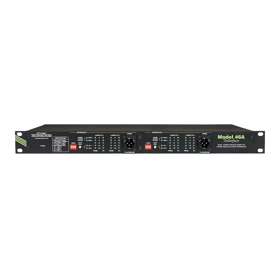
Introduction one space of a standard 19-inch rack enclosure and requires 100-240 volts, The Model 46A is designed to interface 50/60 Hz for operation. 2-wire full-duplex party-line (PL) intercom 2-Wire Interfaces circuits with 4-wire audio circuits associ- ated with matrix intercom systems. Other The Model 46A’s 2-wire interfaces are... - Page 6 “hiss” associ- such as user stations or beltpacks. In this ated with typical intercom power supply type of application the Model 46A is config- performance. Under software control the ured to operate in its external 2-wire power output of the DC power supplies are moni- source mode.
- Page 7 “loop” issues. A key characteristic Whenever a user presses one of the of the Model 46A’s design is the ability to Model 46A’s auto null buttons digital select the 4-wire input and output nominal circuitry adjusts the analog hybrids to levels.
- Page 8 Special Applications noise, and high headroom. Using passive and active filters, the frequency response While the Model 46A is designed to di- is limited to approximately 100 Hz to 8 kHz. rectly integrate into typical applications, This range was selected to provide excel- it’s ready to support the “one-in-a-million”...
- Page 9 (I/O) panel. with a screwdriver, be present during every installation. (It was universally acknowl- The Model 46A is housed in a rugged alu- edged that their time can be better spent minum and steel enclosure that is designed elsewhere!) The need to adjust trim potenti- to be “road tough.”...
-
Page 10: Installation
Another location lation and troubleshooting. And by making criterion is access to the Model 46A’s front the Model 46A “universally” powered, panel. An optimal location will allow con- installation in any locale could be directly venient use of the auto null push buttons supported. - Page 11 0, +4, +6, or +8 dBu. Configuration switches, With an unbalanced source connect pin 2 located on the Model 46A’s front panel, to signal high (+ or hot) and both pins 1 allow the circuitry to be adjusted to match and 3 to shield.
- Page 12 3-pin 2-Channel Intercom Systems male XLR connectors which are located on the Model 46A’s back panel. Refer to If compatibility with RTS TW systems is Figure 1 for a detailed view. desired the mating connectors (females)
- Page 13 3-pin XLR intended to mate with the Model tion of three functions: auto nulling for 46A will connect to pin 1 of both 3-pin male interface 1, auto nulling for interface 2, and XLR connectors. Pin 2 of the female XLR a special “mic kill”...
- Page 14 flowing through it. An D-subminiature type. active remote control input is one that Figure 3. Location of 10-pin male header connector on the Model 46A printed circuit board Issue 1, September 2014 Model 46A User Guide Page 14...
- Page 15 AC Mains Power has current flowing through it for a mini- mum of 30 milliseconds. A special case The Model 46A operates directly from AC arises when the auto null button operating mains power of 100 to 240 V, 50/60 Hz. As mode has been set to independent.
-
Page 16: Configuration
When switch 1 is in its on (up) position the the Model 46A’s front panel. They provide Model 46A will provide a 30 volt, 315 mA identical capability for their respective maximum source of DC power to pin 2 of interfaces. -
Page 17: Advanced Configuration
Specifically, 200 ohm RVON-I/O unit. impedances are automatically applied to both pins 2 and 3 of a Model 46A 2-wire When DIP switches 3 and 4 are in their off party-line interface when that interface is (down) position the nominal level is set for configured for external power and no ex-... - Page 18 DC voltage won’t be present on sent out the 4-wire line output connectors. either pin 2 or 3 and the Model 46A will au- Users of the 4-wire equipment may be less tomatically apply 200 ohm terminations. In...
- Page 19 When DIP switch 2 is in its off (down) posi- each Model 46A interface will often end up tion the dual auto null mode is selected. not routed to the same user device; inde- This is provided specifically for cases where...
-
Page 20: Operation
4-wire connections. The meters are rectly set 4-wire nominal audio level DIP organized in four groups each represent- switches for one or both of the Model 46A’s ing one input and one output. They are interfaces. If the nominal level is set too calibrated to reflect the level in dB relative... - Page 21 2-wire party-line power on pin 2 of the 2-wire connectors, circuits and go out the 4-wire interfaces. An nor will the Model 46A use any power from issue may arise if the signals coming from a connected intercom circuit. As expected, the connected party-line user devices aren’t...
- Page 22 BP-325 use surface mount component assignments can be made. In the external technology and have a lower maximum 2-wire power mode the Model 46A is sim- current draw of 65 mA. Four of these “mod- ply an observer; whether intercom power is ern”...
- Page 23 3 the LED will light. This condition will normally never exist but could prove useful in special circumstances. Auto Null Each of the Model 46A’s 2-channel inter- Figure 10. Detail of front panel showing auto faces has circuitry to automatically null the null section two 2-wire-to-4-wire interfaces.
-
Page 24: Advanced Operation
3. But whether or not either or both LEDs the auto terminate disable and factory test are lit, the Model 46A will never apply 200 modes. ohm terminations to pins 2 or 3. For the... -
Page 25: Technical Notes
1 through 5. The five meter put. While not appropriate during actual LEDs associated with TO 4-wire channel Model 46A use, it is interesting to “hear” 1 of interface 1 are used to display the the nulling process take place. But unless... - Page 26 There’s no doubt that a Model which software version is loaded into the 46A could be used to create a 2-wire-to- Model 46A a trip back to the factory is 2-wire party line “bridge” by cross-link- required to update it. The 8-bit microcon- ing the 4-wire inputs and outputs using troller that provides the unit’s logic “horse-...
-
Page 27: Specifications
Type: transformer-coupled, capacitor isolated Impedance: 13 k ohms Nominal Level: 0, +4, +6, or +8 dBu, selectable in tandem with nominal output level Maximum Level: +22 dBu Model 46A User Guide Issue 1, September 2014 Studio Technologies, Inc. Page 27... -
Page 28: Appendix A-Interfacing With Rts® Matrix Intercom Systems
Appendix A Interfacing RTS® Matrix Intercom Systems with the Model 46A Interface ADAM™ Matrix Intercom System Analog Ports to Model 46A Interface RVON-I/O I/O Connections to Model 46A Interface Issue 1, September 2014 Model 46A User Guide Page 28 Studio Technologies, Inc. -
Page 29: Appendix B-Interfacing With Riedel® Artist™ Matrix Intercom Systems
Appendix B Interfacing Riedel® Artist™ Matrix Intercom System Analog Ports with the Model 46A Interface Model 46A User Guide Issue 1, September 2014 Studio Technologies, Inc. Page 29... -
Page 30: Appendix C-Interfacing With Clear-Com® Matrix Intercom Systems
Appendix C Interfacing Clear-Com® Matrix Intercom System Analog Ports with the Model 46A Interface Issue 1, September 2014 Model 46A User Guide Page 30 Studio Technologies, Inc.
Need help?
Do you have a question about the 46A and is the answer not in the manual?
Questions and answers