
Related Manuals for Studio Technologies 42A


Summary of Contents for Studio Technologies 42A
- Page 1 User Guide Issue 2, December 2013 This User Guide is applicable for serial numbers M42A-01051 and later Copyright © 2013 by Studio Technologies, Inc., all rights reserved www.studio-tech.com 50127-1213, Issue 2...
- Page 2 This page intentionally left blank.
-
Page 3: Table Of Contents
Introduction ..............5 Installation ..............8 Post-Installation ............. 12 Operation ..............13 Troubleshooting ............16 Technical Notes ............. 18 Specifications ..............22 Appendix A ..............23 Block Diagram Model 42A User Guide Issue 2, December 2013 Studio Technologies, Inc. Page 3... - Page 4 This page intentionally left blank. Issue 2, December 2013 Model 42A User Guide Page 4 Studio Technologies, Inc.
-
Page 5: Introduction
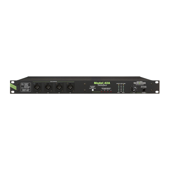
The DC rack-space package is constructed using power source is typically in the range of rugged steel and aluminum components. Figure 1. Model 42A Interface front and back views Model 42A User Guide Issue 2, December 2013 Studio Technologies, Inc. - Page 6 2-channel or stereo audio source. This In many cases, the Model 42A Interface will configuration may prove useful in radio be used in on-air television applications. broadcasting, audio-with-picture, or re- Whether installed in a fixed location or as...
- Page 7 The output power is 30 volts DC with a repeating sequence. maximum current of 220 milliamperes. A DC Monitoring and Fault major strength of the Model 42A is the IFB output’s ability to effectively deliver DC Shut Down power over a variety of conditions. Unlike...
-
Page 8: Installation
Alternate Applications Locating the Model 42A In addition to broadcast intercom applica- tions, the Model 42A can be used to cre- The Model 42A’s IFB outputs provide DC ate high-performance stereo headphone power and unbalanced audio to operate cue systems. - Page 9 Audio input connections are made by way of one female 25-pin D-subminiature con- The Model 42A has eight line-level audio nector which is located on the Model 42A’s inputs, arranged as four 2-channel pairs. back panel. A cable harness is required...
- Page 10 – and the shield pins. If connecting an Notes: unbalanced source in this manner results 1) Connector type on Model 42A is 25-pin D-subminiature in hum or noise, try connecting signal high female. Installer must provide plug (male). Connector uses 4-40 threaded inserts for locking with mating plug.
- Page 11 Figure 5. Detail of back panel showing IFB output connectors on pin 3 also has a nominal signal level of When a Model 42A is used in an equip- –10 dBu. Its audio source is the channel 2 ment rack that will move between broad- audio input associated with that specific...
-
Page 12: Post-Installation
Safety Warning: The Model 42A does impact the DC power supplied by the not contain an AC mains disconnect Model 42A. There’s no way to get around switch. As such, the AC mains cord the fact that some DC voltage will be plug serves as the disconnection dropped in the interconnecting cable(s). -
Page 13: Operation
The Audio Integrity “heart” of the monitor section is logic At this stage the Model 42A should have circuitry created by a microcontroller been installed and the audio source levels integrated circuit along with its associated... - Page 14 firmware. This combination adds “smarts” It’s important to note that the Model 42A’s to otherwise fairly pedestrian functions. meters are calibrated differently from the typical “VU” scale. The level steps were Using four electromechanical relays, the selected to effectively display the IFB audio monitor section accesses the IFB output’s nominal –10 dBu signal level.
- Page 15 2 will be automatically Model 42A IFB outputs using faulty por- skipped. table cabling. Unique to the Model 42A is its auto scan An under-voltage condition that’s pres- feature. Pressing and holding the button ent for a continuous 4-second period will for two seconds will cause this feature to cause a fault condition to be recognized.
-
Page 16: Troubleshooting
If, for example, the auto female XLR connectors that are plugged scan function was active when the Model into the Model 42A’s back panel. If normal 42A was powered down, auto scan will operation then begins, carefully check the begin once AC mains power is again IFB output wiring for fault conditions. - Page 17 In extreme cases, such timally. Applying signal levels significantly as when the Model 42A is located in an higher than +4 dBu will reduce the head- environment with elevated temperatures, room and greatly increase the chance of a few minutes may be required from the reaching audio “clipping.”...
-
Page 18: Technical Notes
IFB user devices. Either Software Version Display a defective user device can be draw- A special Model 42A power-up sequence ing too much current or too many user allows the unit’s software version number devices end up being connected to the to be displayed. - Page 19 Note that while it’s easy to determine which software version is loaded into Let’s use the example of a Studio Technol- the Model 42A a trip back to the factory ogies Model 210 Announcer’s Console is required to update it. The 8-bit micro- being connected to a Model 42A IFB controller that provides the unit’s logic...
- Page 20 For example, a 1000-foot reel of 24-gauge 2-pair unshielded tele- As previously discussed, one of the Model phone cable was used to link a Model 42A 42A’s strengths is its ability to very effec- IFB output with an IFB user device. One...
- Page 21 It’s not hard to notice the 4010 Model 42A Model 41 Current (mA) Figure 10. IFB output voltage-current curves for RTS 4000-Series and Model 42A Interface Model 42A User Guide Issue 2, December 2013 Studio Technologies, Inc. Page 21...
-
Page 22: Specifications
Pin 3: +14 dBu with +28 dBu on audio input Specifications and information contained in this DC Current Output: 220 mA maximum User Guide subject to change without notice. Issue 2, December 2013 Model 42A User Guide Page 22 Studio Technologies, Inc. -
Page 23: Appendix A
Appendix A Interfacing Riedel® Artist™ Matrix Intercom Systems with the Model 42A Interface Information courtesy of Riedel Communications Inc. Model 42A User Guide Issue 2, December 2013 Studio Technologies, Inc. Page 23...
Need help?
Do you have a question about the 42A and is the answer not in the manual?
Questions and answers