Table of Contents
Advertisement
<Important>
Be sure to correctly follow the procedures in order as explained in this Installation Manual.
If you do not follow the procedure in order, the image trouble may occur.
I. Outline of installation procedures
PC-107
AU-101
WT-506
AU-102
WT-507
AU-201
SP-501
JS-603
PK-517
FS-527
SD-509
When installing the machine and associated options as a system, follow the order shown on the upper.
Note:
• For the detailed installation procedures for each
option, follow the instructions given in the corre-
sponding installation manual and perform the
procedures correctly. (Optional devices must be
installed after completing the main body instal-
lation.)
• When placing the machine on the floor, make
sure to use the paper feed cabinet or the desk
to secure the performance and the quality of
the product.
• To use this machine, install the reverse auto-
matic document feeder or the original cover.
Even if you do not install the original cover, be
sure to install the hinge covers furnished with
the original cover.
• Once the Power Switch is turned ON, do not
turn OFF it until the installation work has been
completed.
• Lifting the machine in an awkward position or
transporting it in a poorly balanced position
Y111050-6
d-Color MF360/MF280/MF220
INSTALLATION MANUAL
PC-207
PC-408
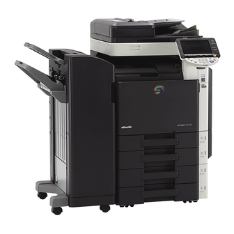
Machine
*2
KH-101
DF-617
Electron system options
FS-529
Applied Machines:d-Color MF360/MF280/MF220
DK-507
MK-713
OC-509
JS-505
*1
: No particular order in installation procedures.
*2
: Varies depending on the applicable marketing area.
*3
: Unable to be installed in d-Color MF220.
*4
: For D-Color MF220 only.
could result in personal injury. When transport-
ing the machine, assign an adequate number of
persons to the job and ensure that each person
can take a good position of not being exces-
sively loaded.
(mass: approx. 98 kg (216-1/16 lb))
E-1
✱ Electron system options
*1
*1
EK-604
EK-605
*1
UK-203
*3
VI-505
*4
HD-515
MK-720
SC-507
*3
IC-412
Installation Manual
FK-502
A0EDIXC041DA
Advertisement
Table of Contents

Related Manuals for Olivetti d-Color MF360


Summary of Contents for Olivetti d-Color MF360
-
Page 1: Installation Manual
MF360/MF280/MF220 INSTALLATION MANUAL Applied Machines:d-Color MF360/MF280/MF220 <Important> Be sure to correctly follow the procedures in order as explained in this Installation Manual. If you do not follow the procedure in order, the image trouble may occur. I. Outline of installation procedures... -
Page 2: Accessory Parts
II. Installation space (unit: mm (inch)) IV. Accessory parts d-Color MF360 + DF-617 + PC-207 + FS-527 Name Q’ty SD-509 + MK-713 1. User’s guide holder 1909 (75-3/16) 2. Quick guide (Copy/Fax/Scan/Box operations) * (25-7/8) (39) (10-1/4) 3. Installation manual 1 set 4. -
Page 3: Removing The Machine
V. Removing the machine VI. Removing protective tape, packing and other shipping materials / Installing the 1. Unpack and remove the machine package. 2. Remove the machine, holding it by the locations control panel on the left side and the handles on the right side 1. - Page 4 2. Open the right door and remove the protective 4. Install the furnished control panel. Note: sheet and packaging materials. Note: Insert the hook of the control panel into the posi- After removing the packaging materials, make tioning hole of the machine. sure that the transfer roller assy is secured in place.
- Page 5 7. Remove the protective sheet. 10. Open the front door and remove the protective tape. A0EDIXC011DA 8. Slide out the 1st drawer and remove protective tape from the inside of the drawer. A0EDIXC014DA 11. Remove the protective materials from the four places.
-
Page 6: Installing The Toner Cartridge
13. Slightly slide the drum unit (K) out and remove 2. Insert the toner cartridge into the machine. Note: the protective tape. • Make sure that the color is same between inserting port and the toner cartridge. • Make sure that the blue label position of the toner cartridge is matched with the one of the machine side. -
Page 7: Installing The Waste Toner Box
VIII. Installing the waste toner box IX. Mounting the accessory parts 1. Remove the protective tape from the furnished 1. Attach the cap A and B furnished with the waste toner box. machine. A0EDIXC024DA A0EDIXC026DA 2. Install the waste toner box. 2. -
Page 8: Connecting The Power Cord
XI. Installing the set guide for banner 2. Connect the power cord. paper 1. Affix a furnished label to the set guide for banner paper as shown in the illustration. Note: Select a label that fits onto the machine from the furnished labels. -
Page 9: Toner Supply
XIII. Toner supply 4. Touch “OK.” 5. Touch “Exit” on the Service Mode screen. 1. Turn ON the Main Power Switch and then Sub 6. Turn OFF and ON the Main Power Switch. Power Switch. Note: 2. Display the Service Mode screen. When displayed the Service Mode screen, be sure (For details of how to display the Service Mode to turn off the main power after exiting the Service... - Page 10 × <If A3 or Ledger paper is set in step 1> 12. Touch “Copy”, select “A3 ”, and × 6. Touch “Print”, select “A3 ”, and press the start key. A test pattern will then be produced on the press the start key. or Ledger paper.
- Page 11 ½×11 <If A4 or Letter paper is set in step 1> 12. Touch “Copy”, select “A4 ”, and press the start key. ½×11 6. Touch “Print”, select “A4 ”, and A test pattern will then be produced on the two press the start key.
-
Page 12: Date/Time Setting
XVII. Date/Time setting XIX. Serial number input Note: 1. Make sure that the Service Mode screen is dis- played. Serial number input is needed only for optional 2. Display the Date & Time Setting screen. devices that will be installed later. (To display the Date &... -
Page 13: Affixing The Paper Size Label
XXII. Affixing the paper size label XXIV. Adjusting registration of paper source options Affix the paper size label. <1 way paper feed cabinet, large capacity cabinet> 1. Display the Service Mode screen. (For details of how to display the Service Mode screen, see the service manual.) 2. - Page 14 10. If the measured width A falls outside the speci- 9. Measure width A of the test pattern on the back- fied range, enter the correction value using the side of the test print produced and check that it falls within the specified range. key.
-
Page 15: Connecting Cables
XXVI. Connecting cables 3. Connect the networking equipment (HUB) using the network cable. 1. Remove the knockout from the cover located on Note: the right side of the machine with nippers as The following shows the recommended network shown in the illustration. cables that correspond to each communication Note: speed.
Need help?
Do you have a question about the d-Color MF360 and is the answer not in the manual?
Questions and answers