Table of Contents
Advertisement
Quick Links
Advertisement
Table of Contents

Related Manuals for Olivetti d-Copia 12


Summary of Contents for Olivetti d-Copia 12
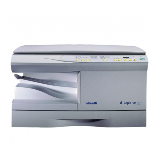
- Page 1 Copier d-Copia 12 SERVICE MANUAL Code Y101700-5...
- Page 2 PUBBLICATION ISSUED BY: Olivetti TECNOST S.p.A. Documentazione 77, Via Jervis - 10015 Ivrea (Italy) Copyright © 2002, Olivetti All rigths reserved...
- Page 3 CAUTION This product is a class 1 laser product that complies with 21CFR 1040.10 and 1040.11 of the CDRH standard and IEC825. This means that this machine does not produce hazardous laser radiation. The use of controls, adjustments or performance of procedures other than those specified herein may result in hazardous radiation exposure.
- Page 4 Service Manual Y101700-5...
-
Page 5: Main Features
1. GENERAL 1.1 Main features The d-Copia 12 copier has the following major - Substancial copying functions characteristics: · Zoom copying from 50% to 200% in 1% increments can be performed. · A maximum of 99 copies can be selected. -
Page 6: Specifications
1.2 Specifications 1.2.1 Basic specifications of the copier A. Basic specifications Item Spec. Type Desktop Copy system Dry, electrostatic Segment (class) Digital personal copier External dimensions (W × D × H) (mm) 518 mm × 482.6 mm × 292.6 mm Weight Approx. - Page 7 Section Item Details Spec. Paper exit Exit way Face down section Capacity of output tray 100 sheets Original set Center Registration (left edge) B4 (10″ × 14″) Max. original size Originals Original kinds sheet Original size detection None Scanning system CCD sensor scanning by lighting lamp scanner CCD sensor...
- Page 8 C. Copy performance Section Item Details Spec. Copy Fixed magnification ratios 3R + 2E (AB system: 50, 70, magnification 81, 100, 141, 200%) (Inch system: 50, 64, 78, 100, 129, 200%) 50 ∼ 200% (151 steps in 1% Zooming magnification ratios increments) Manual steps (manual, 5 steps...
-
Page 9: Supply System Table
1.3 Consumables 1.3.1 Supply system table Name Content Life Package Toner CA (Black) Toner 6.5K with CA (Toner Net Weight 210g) per unit Polyethylene bag Developer Developer (Developer Net Weight 170g) per unit Drum kit Drum Drum fixing plate Note: Packed together with the machine: DR 25K/Developer UN/Process UN. Y101700-5 Service Manual... -
Page 10: Environmental Conditions
1.4 Environmental conditions 1.5 Production control number (lot No.) identification The environmental conditions for assuring the copy quality and the machine operations are as follows: (Developing cartridge) - Normal operating condition • Temperature:20°C~25 • Humidity:65 ± 5%RH - Acceptable operating condition *: Destination Division EX Destination... -
Page 11: Td Cartridge Replacement
1.6 TD cartridge replacement Division 1) Open the front and side cabinets of the copier. Ex production 2) Keep holding Toner lover, and Option 3) Carefully pull out Toner unit from the copier. Same pack 4) Put Toner unit in a collection bag immediately after removing it from the copier. -
Page 12: General Appearance
1.7 External views and internal components 1.7.1 General appearance Original cover 12 Paper output tray extension Side cover 13 Handle Manual bypass 14 Power switch Paper guides 15 Power cord socket Side cover open button 16 Toner cartridge lock release lever Front cover 17 Toner cartridge Paper tray... -
Page 13: Operation Panel
1.8 Operation panel 8 ON LINE indicator Exposure mode selector key and indicators Use to sequentially select the exposure modes: AUTO, MA- Lights up when the machine is used as a printer or when it is NUAL ( = ) or PHOTO ( ). -
Page 14: Motors And Solenoids
1.9 Motors and solenoids Part name Control signal Function operation Toner motor Supplies toner Mirror motor MRMT Drives the optical mirror base (scanner unit) Cooling fan motor Cools the optical section Main motor Drives the copier Resist roller solenoid Resist roller rotation control solenoid Paper feed solenoid CPFS1 Cassette paper feed solenoid 1... -
Page 15: Sensors And Switches
1.10 Sensors and switches Name Signal Type Function Output Mirror home Mirror (scanner unit) position sensor MHPS Transmission sensor home pos. detection “H” at home pos. POD sensor Transmission sensor Paper exit detection “H” at paper pass SPPD sensor SPPD Transmission sensor Paper transport detection “L”... -
Page 16: Pwb Unit
1.11 PWB unit Name Function Exposure lamp invertor PWB Exposure lamp (Xenon lamp) control GDI PWB For GDI interface Main PWB (MCU) Copier control Memory PWB 4MB For memorizing data LSU PWB For laser control LSU motor PWB For polygon motor drive TCS PWB For toner sensor control Operation PWB... -
Page 17: Cross Sectional View
1.12 Cross sectional view Part name Function and operation Paper exit roller Roller for paper exit Lens unit Scans the original image with the lens and the CCD LSU (Laser unit) Converts the original image signal into laser beams and writes onto the drum Main charger Provides negative charges evenly to the drum surface... - Page 18 1-14 Service Manual Y101700-5...
-
Page 19: Unpacking And Installation
2. UNPACKING AND INSTALLATION 2.1 Copier installation Improper installation may damage the copier. Please note the following during initial installation and whenever the copier is moved. Caution: If the copier is moved from a cool place to a warm place, condensation may form inside the 2.2 Cautions on handling copier. -
Page 20: Checking Packed Components And Accessories
2.3 Checking packed components and 2) Use a coin (or suitable object) to remove the screw. Store the screw in the paper tray because it will be used if accessories the copier has to be moved. Open the carton and check if the following components and accessories are included. -
Page 21: Toner Cartridge Installation
9) Shake the aluminum bag to stir developer. 2.7 Toner cartridge installation 10) Supply developer from the aluminum bag to the top of the MX roller evenly. 1) To prevent against uneven distribution of toner, hold Toner unit with both hands and shake it several times horizontally. -
Page 22: Loading Copy Paper
6) Pull out the shutter in the arrow direction. 5) Fan the copy paper and insert it into the tray. Make sure the edges go under the corner hooks. Note: Do not load paper above the maximum height line ). Exceeding the line will cause a paper misfeed. Note: Do not hold and carry the shutter. -
Page 23: Operational Descriptions
3. OPERATIONAL DESCRIPTIONS 3.1 Outline of operation The outline of operation is described referring to the basic configuration. Outline of copy operation Setting conditions 1) Set copy conditions such as the copy quantity and the copy density with the operation section, and press the COPY button. The information on copy conditions is sent to the MCU. -
Page 24: Scanner Section
3.2 Scanner section 3.2.1 How to scan documents The scanner has sensors that are arranged in a line. These sensors scan a certain area of a document at a time and deliver outputs sequentially. When the line is finished, the next line is scanned, and this procedure is repeated. -
Page 25: Laser Unit
3.3 Laser unit Makes the laser scanning speeds at both ends of the drum same as each other. The image data sent from the MCU (image process circuit) is sent to the LSU (laser unit), where it is converted into laser beams. 3.3.1 Basic structure The LSU unit is the writing section of the digital optical system. -
Page 26: Fuser Section
3.4 Fuser section (3) Thermal control 1. The heater lamp, thermistor, main PWB, DC power supply PWB, and triac within the power supply unit are used to control the temperature in the fuser unit. To prevent against abnormally high temperature in the fuser unit, a thermal breaker and thermal fuse are used for safety purposes. -
Page 27: Paper Feed Section And Paper Transport Section
3.5 Paper feed section and paper transport section 3.5.1 Paper transport path and general operations Scanner unit Main charger (11) Pickup roller Copy lamp Heat roller (12) Manual paper feed roller Lens unit Pressure roller (13) PS roller unit LSU (Laser unit) Drum (14) Paper feed roller... - Page 28 3.5.2 Cassette paper feed operation 5) At this time, the paper is fed past the paper entry detection switch (PPD1), and detected by it. After about 0.15 sec 1) The figure below shows the positions of the pick-up from detection of paper by PPD1, the tray paper feed roller, the paperfeed clutch sleeve, and the paper feed solenoid (PFS) turns on so that the clutch sleeve projection latch in the initial state without pressing the COPY...
-
Page 29: Disassembly And Assembly
4. DISASSEMBLY AND ASSEMBLY 2) Remove the drum fixing plate and the photoconductor drum. Note: Dispose the drum fixing plate which was removed. Before disassembly, be sure to disconnect the power cord for safety. The disassembly and assembly procedures are described for the followingn sections: 1. - Page 30 5) Remove the cleaning blade. Attach the mocket with slightly pressing the cleaning blade. Note: Dispose the cleaning blade which was removed. Do not touch the tip of the cleaning blade. Do not put the mocket under the cleaning blade. Do not put the mocket on the sub blade.
-
Page 31: Disassembly Procedure
4.1.3 Disassembly procedure (2) Push up the lock pawls (2 positions) of the side cover, and remove the transfer charger. (1) Press the side cover open/close button and open the side cover. 4.1.4 Assembly procedure For assembly, reverse the disassembly procedure. 4.1.5 Charger wire cleaning (1) Remove the charger cleaner from the manual paper feed unit. -
Page 32: Operation Panel Section
(2) Set the charger cleaner to the transfer unit, and move it 4.2 Operation panel section reciprocally a few times in the arrow direction shown in the figure below. 4.2.1 List of parts Part name Ref. Operation panel unit Operation PWB 4.2.2 Disassembly procedure (1) Remove the screws (4 pcs.), the harness, and the operation panel unit. -
Page 33: Optical Section
4.2.3 Assembly procedure (2) Remove the screws (2pcs.), and remove the copy lamp unit from the mirror base drive wire. For assembly, reverse the disassembly procedure. 4.3 Optical section 4.3.1 List of parts Part name Ref. Copy lamp unit Copy lamp Lens unit 4.3.2 Disassembly procedure (1) Remove the parts as shown below. -
Page 34: Fusing Section
(5) Remove the screws (2 pcs.), the harness, and the optical 4.4 Fusing section unit. 4.4.1 List of parts Part name Ref. Thermistor PPD2 sensor Heater lamp Pressure roller Heat roller 4.4.2 Disassembly procedure (1) Remove the connectors (3 pcs.) of the rear cabinet. (2) Open the side cover, remove two screws, and remove the fusing unit. - Page 35 (4) Remove the screw and remove the U-turn guide. (7) Remove the plate spring on the right and remove the heater lamp. 4.4.2.1 Pressure roller section disassembly (5) Remove the three screws, remove the fusing cover lower on the right side, and open the heat roller section. (8) Remove the spring and remove the separation pawls (3 pcs).
-
Page 36: Assembly Procedure
(10) Remove the pressure release levers on the right and the (6) Remove the C-ring and the fusing bearing, and remove left sides. the heat roller. (7) Remove the parts from the heat roller. Note: Apply grease to the sections specified with (11) Remove the pressure roller, the pressure bearing, and the spring. - Page 37 4.5 Cassette paper feed/transport section (3) Remove two screws and remove the toner motor. 4.5.1 List of parts Part name Ref. PPD1 sensor PWB LSU unit Intermediate frame unit Paper feed roller 4.5.2 Disassembly procedure (1) Remove six connectors and screws of the main PWB, and lift the optical unit and the main PWB to remove.
- Page 38 (5) Remove the pulleys on the both sides and remove the (7) Release the belt pulley lock and remove the belt pulley paper exit roller. bearing. (6) Pull out the paper exit roller knob and remove the belt. (8) Remove the paper exit roller. 4-10 Service Manual Y101700-5...
- Page 39 (9) Remove the harness guide. (11) Remove the parts as shown below, and remove the pressure release solenoid and the paper feed solenoid. (10) Remove five screws and remove the main drive plate and the belt. (12) Remove six screws and remove the LSU unit. Y101700-5 Service Manual 4-11...
- Page 40 (13) Remove two screws and remove the fusing connector. (17) Remove three screws and remove the TC front paper (14) Remove five screws and the connector, and lift the guide. intermediate frame unit to remove. (18) Remove the screw and the connector, and remove the PPD1 sensor PWB.
-
Page 41: Manual Paper Feed Section
(19) Remove two E-rings and remove the paper feed roller. 4.6 Manual paper feed section (20) Remove three E-rings and remove the clutch unit. 4.6.1 List of parts Part name Ref. Manual transport roller Cassette detection switch PPD1 sensor PWB Side door detection unit 4.6.2 Disassembly procedure (1) Remove the screw and remove the single upper cover. - Page 42 (2) Remove the screw and remove the side door detection (4) Remove the PPD1 sensor PWB. unit. (3) Remove three screws and remove the single manual feed upper frame. (5) Remove the E-ring and remove the manual paper feed transport roller. 4-14 Service Manual Y101700-5...
-
Page 43: Rear Frame Section
(6) Remove the cassette detection switch. 4.7 Rear frame section 4.7.1 List of parts Part name Ref. Mirror motor Main motor Exhaust fan motor 4.7.2 Disassembly procedure (1) Remove three screws and remove the rear cabinet. (2) Remove two screws, the harness, and the mirror motor. (7) Remove the multi cover. -
Page 44: Power Section
(3) Remove two screws and one harness, and remove the 4.8 Power section main motor. 4.8.1 List of parts Part name Ref. Power PWB 4.8.2 Disassembly procedure (1) Remove two screws and one connector, and remove the power PWB. (4) Remove two screws and one connector, and remove the exhaust fan motor. -
Page 45: Image Distortion Adjustment
5. ADJUSTMENTS 5.1.1.3 Adjustment procedure 1) Remove the right cabinet (manual paper feed unit), the document reference plate. 5.1 Image distortion adjustment 2) Remove the document glass. There are following two types of image distortion. • Horizontal image distortion • Vertical image distortion In this machine, the image distortion is adjusted by changing the parallelism of mirrors (copy lamp unit, No. - Page 46 7) Manually turn the copy lamp unit/No.2/3 mirror unit drive gear to bring No.2/3 mirror unit into contact with the positioning plate, and perform the procedure of step 4. Repeat procedures of steps 4 to 7 until the parallelism of No.2/3 mirror unit is properly set.
- Page 47 10) Check the horizontal image distortion. 5.1.2 Vertical image distortion adjustment If LL = LR, there is no horizontal distortion In this adjustment, the left and right balance is adjusted by changing the left and right balance of the No. 2 scanner unit frame on the front frame side.
-
Page 48: Copy Magnification Ratio Adjustment
3) If the right-left distortion balance is improper, loosen the The main scanning (front/rear) direction magnification ratio fixing screw of No.2/3 mirror unit rail to change and adjust adjustment is made automatically or manually. the right-left balance of No.2/3 mirror unit rail. Automatic adjustment: The width of the reference line marked on the shading correction plate is scanned to perform the main scanning (front/rear) direction magnification ratio adju-... - Page 49 4) Measure the length of the copied scale image. 5) Calculate the main scanning direction magnification ratio. Main scanning direction magnification ratio Copy image dimensions × 100 (%) Original dimension 6) Check that the copy magnification ratio is within the 5.2.2.1 Cases when the adjustment is required specified range.
-
Page 50: Image Position Adjustment
5.2.4 Image position adjustment 6) Check that the actual copy magnification ratio is within the specified range. (100 ± 1.0%). There are following five kinds of image position adjustments, If it is not within the specified range, perform the following which are made by laser control except for the image scan procedures. - Page 51 The relationship between the adjustment modes and the lighting lamps are as shown in the table below Machine with the multi manual paper feed unit. Adjustment mode Lighting lamp Print center offset (cassette) Auto, Cassette Print center offset (manual feed) Auto, Manual Document center offset Auto, Manual...
-
Page 52: Note For Copy Density Adjustment
5.3.2 Note for copy density adjustment 5.3.2.1 Arrangement before execution of the copy density adjustment • Clean the optical section. • Clean or replace the charger wire. • Check that the voltage at the high voltage section and the developing bias voltage are in the specified range. 5.3.3 Necessary tool for copy density adjustment 2) Execute SIM 50 –... -
Page 53: Copy Density Adjustment Procedure
5.3.5 Copy density adjustment procedure Use SIM 46-01 to set the copy density for each copy mode. For selection of modes, use the copy mode select key. 5.3.5.1 Test chart (UKOG-0162FCZZ) setting 1) Place the test chart so that its edge is aligned with the A4 (Letter) reference line on the document table. -
Page 54: High Voltage Adjustment
5.4 High voltage adjustment 5.4.2 DV bias adjustment • A digital multi meter with internal resistance of 1GW 5.4.1 Main charger (Grid bias) must be used for correct adjustment. • Use a digital multi meter with internal resistance of 5.4.2.1 Procedures 10MW or more measurement. -
Page 55: Simulations And Trouble Codes
6. SIMULATIONS AND TROUBLE CODES 6.1 Simulations 6.1.1 List of simulations Sim No. Kind of main code Sub code Operation Optical system Mirror scan operation Lamp ON Operation panel display check check Fusing lamp ON + Cooling fan HIGH/LOW speed Copy lamp ON Machine Paper feed solenoid ON... - Page 56 Sim No. Kind of main code Sub code Operation Various setup Manual feed setup SPF setup Second cassette setup Machine duplex setup Destination setup Machine conditions check Rear edge void setup CE mark conformity control ON/OFF setup Cancel of stop at developer over Memory capacity setup Polygon motor OFF time setup Transfer ON timing control setup...
- Page 57 Main code Sub code Content Mirror scan operation (Operation/Procedure) 1. When this simulation is executed, the mirror home position is detected. Sensor name Display lamp Mirror home position sensor OPC drum cartridge replacement lamp 2. When the _START key is pressed, scanning is executed at the speed corresponding to the currently set copy magnification ratio.
- Page 58 Main code Sub code Content Developing bias (Operation/Procedure) When the START key is pressed, the developing bias is outputted for 30 sec. Main charger (Grid high) (Operation/Procedure) When the START key is pressed, the main charger output is supplied for 30 sec in the grid Grid voltage (Low) (Operation/Procedure)
- Page 59 Main code Sub code Content Maintenance/mini-maintenance counter display The display is the same as the total counter value display. When the destination is set to other than Japan AB series, the maintenance counter is displayed. When the destination is set to Japan AB series, the mini-maintenance counter is displayed.
- Page 60 Main code Sub code Content Main motor system ON + Cooling fan low speed (Operation/Procedure) When the START key is pressed, the main motor is rotated for 30 sec. To save toner consumption, the different operations are executed depending on installation of the developing unit.
- Page 61 Main code Sub code Content Machine duplex setup (Operation/Procedure) 1. When this simulation is executed, the currently set duplex code number is displayed. 2. Enter the code number corresponding to the duplex and press the ENTER key and the setup will be changed. Code number Duplex Without duplex...
- Page 62 Main code Sub code Content Rear edge void setup (Operation/Procedure) 1. When this simulation is executed, the currently set code number of rear edge void setting is displayed. 2. Enter the code number of rear edge void setting and press the START key, and the setting will be changed.
- Page 63 Main code Sub code Content Polygon motor OFF time setup (Operation/Procedure) 1. When this simulation is executed, the currently set code number is displayed. 2. Enter the code number and press the START key, and the setting will be changed. Code number Setting 0 sec...
- Page 64 Main code Sub code Content Paper sensor status display The paper sensor status is displayed with the lamps on the operation panel. Display Sensor Toner cartridge replacement lamp Paper detection before resist (PPD1) JAM lamp Fusing section paper detection (PPD2) Developer cartridge replacement lamp Paper exit paper detection (POD) AE lamp...
- Page 65 Main code Sub code Content Copy density adjustment (Outline) Used to adjust the copy density in each copy mode. (The copy density can be set by changing the set value of ASIC GAMMA ADJUST register.) Setting in each copy mode is performed at exposure level 3. When the copy density (exposure) is adjusted arbitrarily, the max, and min.
- Page 66 Main code Sub code Content Gamma table setup When this simulation is executed, the currently set gamma table code number is displayed. Enter the code number corresponding to your desired gamma table and press the PRINT switch, and the setup will be changed. Code number Gamma table Japan...
- Page 67 Main code Sub code Content Lead edge image position adjustment + Paper lead edge/rear edge void adjustment (Outline) This adjustment is used to adjust the copy image position and lead edge/rear edge void amount on the copy paper by adjusting the image scan start position and the print start position (resist roller ON timing) at 100%.
- Page 68 Main code Sub code Content Paper center offset + OC/Document center offset (Outline) The center offset position of copy image on the copy paper and that of document scan are adjusted by adjusting the scan left margin of ASIC and the print left margin register set value. (Operation/Procedure) 1.
- Page 69 Main code Sub code Content Self print only with the engine (1 by 2 mode) (Outline) Used to print in the 1 by 2 mode by ignoring the state of the optical system. (Operation/Procedure) 1. When this simulation is executed, warming up is made and the ready lamp is lighted. 2.
-
Page 70: Trouble Codes
6.2 Trouble codes 6.2.1 List of Trouble Codes Main code Sub code Trouble content Detail of trouble HSYNC not detected. LSU (laser diode, reception element, APC circuit) trouble LSU drive circuit (ASIC) trouble CCD white level trouble CCD drive circuit (CCD PWB, ASIC harness) trouble Copy lamp lighting trouble (Copy lamp, invertor PWB) CCD black level trouble CCD drive circuit (CCD PWB, ASIC, harness) trouble... - Page 71 Main code Sub code Trouble content Detail of trouble Counter sum check error. When the counter check sum value stored in the EEPROM is abnormal. EEPROM serial When a communication trouble occurs with the EEPROM. communication error Y101700-5 Service Manual 6-17...
-
Page 72: Maintenance
7. MAINTENANCE 7.1 Maintenance table 7.2 Maintenance display system Y101700-5 Service Manual... - Page 73 1-14 Service Manual Y101700-5...
-
Page 74: Electrical Section
8. ELECTRICAL SECTION 8.1 Block diagram 8.1.1 Overall block diagram Y101700-5 Service Manual... - Page 75 8.2 MCU PWB unit Service Manual Y101700-5...
-
Page 76: User Program
9. USER PROGRAM The conditions of factory settings can be changed according to the use conditions. 9.1 Functions that can be set with the user program Function Contents Factory Setting Auto clear time When a certain time is passed after the completion of copying, this 60 sec function returns to the initial state automatically. - Page 77 3) Press the Print ( ) key. The entered program number will be steadily lit and the currently selected parameter number for the program will blink on the right side of the display. 4) Select the desired parameter using the right copy quantity ( ) key.
- Page 78 UPDA A A A A TING ST TING ST TING ST TING STA A A A A TUS TING ST DATE PAGES UPDATED PAGES CODE 02/2002 EDITION Y101700-5...
Need help?
Do you have a question about the d-Copia 12 and is the answer not in the manual?
Questions and answers