Table of Contents
Advertisement
Advertisement
Table of Contents

Related Manuals for Interlogix NX-595E


Summary of Contents for Interlogix NX-595E
- Page 1 NX-595E Installation Manual P/N 230242 • REV C • ISS 02JUL14...
- Page 2 Americas Corporation, Inc., except where specifically permitted under US and international copyright law. Trademarks and The NX-595E name and logo are trademarks of UTC Fire & Security patents Americas Corporation, Inc. NX-595E name is a trademark of UTC Fire & Security Americas Corporation, Inc.
-
Page 3: Table Of Contents
Using a Standard Keypad (Icon or LCD) 18 Enrolling the NX-595E 19 Accessing the NX-595E – via a Touch Tone Phone 19 Main Menu – Structure 20 Main Menu - Additional Installer Information 21 ... - Page 4 Accessing the NX-595E - via the Web pages 24 Find the IP Address 24 Set the IP Address 24 Navigating to the NX-595E 24 Sign in Page 25 Main Menu (Web) – Accesssed with Installer Code 25 ...
-
Page 5: Important Information
The quantity, quality, and placement of security devices attached to this security system. • The knowledge you have of the security system and how that knowledge is utilized in a weekly test of the complete system. This product is to be installed by qualified SERVICE PERSONNEL only NX-595E Installation Manual... -
Page 6: Disclaimer
A level of TCP IP knowledge is required by the installer/s to set up some of the NX-595E functionality. UTCSF limits it support to NX-595E setup only, and is unable to offer further assistance on your client's DSL modem, router, firewall or any other 3 party software. -
Page 7: Introduction
Introduction The NX-595E is an optional module that may be added to your NetworX security system to provide remote access and reporting features. You can also integrate the security system to devices such as intercom, doors, lighting and air- conditioning via low-level relays. -
Page 8: Features & Benefits
No more confusing beeps or sirens! • Dial up control – The NX-595E can be access by any outside touch tone telephone and once connected the inbuilt Personal Voice Guide (PVG) will navigate you through all available menu options. From basic Arming / Disarming control, to more advanced menus like zone bypassing and System recordings. -
Page 9: Phone Line Connection, And Network Connection
• NX-595E Web Interface – Once connected to the network, users will enjoy the simple web user interface that is supplied with the NX-595E. Enter the IP address of your NX-595E into a web browser to access the NX-595E Configuration Server. Here the user can configure pin codes, arm and disarm partitions, view the last 185 event history, enter and change all voice, and divert phone numbers and assign email address. - Page 10 • NX-181xx Voice keypads can be configured to answer a call initiated from either of the two door stations, they can also control the NX-595E modules onboard door release relays. • Remote listen in / two way communication – this feature allows users to connect to any or all of the connected NX-181xx Voice keypads from a remote location an “listen-in”...
-
Page 11: Installing The Nx-595E Into The Enclosure
Installing The NX-595E into the enclosure Inside the NetworX enclosure, several 2-holed insertion points have been constructed. This allows for either vertical or horizontal placement of the modules. Notice that the insertion points have two sizes of holes - a larger hole and a smaller hole. -
Page 12: Wiring The Nx-595E
POS, COM & DATA to the NetworX bus. A 5-wire interconnecting cable is supplied with the NX-595E. Connect one end to J1 (Audio Tap) on the NX-595E and the other end to J4 (Audio Tap) on the NetworX board. - Page 13 Figure 6 NX-V3 Terminal Strip Important: Ensure the trace is aligned with pin 1 on both panel and NX-595E audio taps. NX-595E Installation Manual...
-
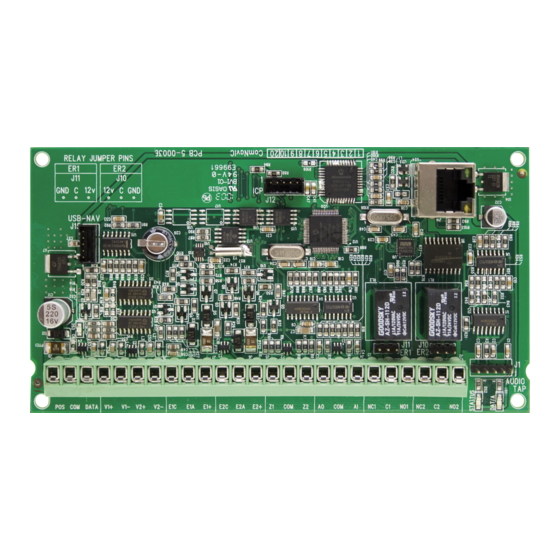
Page 14: Pcb Layout
13 E2+ Positive terminal on outdoor Blue station 2 14 Z1 Zone 3K3 = Single EOLs 3K7 = Low zones 15 Com Additional Common (-) return for Zone Zones loop 6K9 = High zones 16 Z2 Zone NX-595E Installation Manual... -
Page 15: Wiring Structure
1 Relay 1 22 NO1 Normally open 23 NC2 Normally closed This relay is controlled from the NX-181xx communicating 24 C2 Entry Common with outdoor station 2 Relay 2 25 NO2 Normally open Wiring Structure Figure 8 NX-595E Installation Manual... -
Page 16: Faq - Frequently Asked Questions
Video Intercom Monitor requires independent power source FAQ - Frequently Asked Questions 1. If I am upgrading from a previous version of NX-595E what do I need to do? The new NX-595E will automatically configure itself in the cloud and provide email and remote access services without further configuration. -
Page 17: Loading Factory Defaults (Device 191)
IP address is not used by another device. d. Put the NX-595E into program mode by using a keypad and enter device 191. By default this is an extra layer of security to prevent unauthorised remote access. -
Page 18: Using A Nx-181Xx Voice Keypad
[ 9 ][ 1 ][ 0 ] Defaults the device, Note: only required once [ENTER] You are now ready to begin NX-595E programming [MENU] Moves back to step 4, select a device number Moves back to step 3, Advanced system configuration [MENU] selection. -
Page 19: Enrolling The Nx-595E
/ rings have been reached. When the desired number of calls / rings has been reached the NX-595E will grab the phone line and announce the following. -
Page 20: Main Menu - Structure
NX-595E, which will now answer the next incoming call. The second call must be made within 60 seconds of the first call. An installer code is unrestricted and can access all partitions of the NX-595E, including menu 0.0 “Panel and device configuration”. -
Page 21: Main Menu - Additional Installer Information
Additional relay boards (NX-507) can be added, with a system total of 16. An output from a NX-181xx or NX-595E is an X10 command that can be tied to different relays. Set the relay you wish to control to follow event 56 (follow X10 command). -
Page 22: Service Provider Phone Number
How to: Enter Service provider phone number Step Example Enter service provider phone numbers Call the NX-595E via an offsite touch-tone phone to [PIN] begin the session. Press [0] for system configuration menu Press [5] for phone number configuration... -
Page 23: Panel And Device Configuration
To record a new eit message, from the Voice message Step Example recording menu Call the NX-595E via an offsite touch-tone phone to begin [PIN] the session. Press [0] for system configuration menu Press [0] for panel and device configuration... -
Page 24: Accessing The Nx-595E - Via The Web Pages
Location 21 – NX-595E IP Address Location 22 – Subnet Mask Navigating to the NX-595E Enter the IP address of your NX-595E into the web browser to access the NX- 595E Configuration Server. Note: You may also connect using SSL or Secure Sockets Layer by typing https: instead of http: for higher security communications between your browser and the NX-595E. -
Page 25: Sign In Page
Figure 9 Sign in Page When successfully connected, the NX-595E will display the “Sign in Page”. Enter the correct username/password combination to login. • Default Installer Username: installer (username is case sensitive) • Default Password: 9713 (enter the NetworX panel programming code) The default installer name can be changed on the Location Setup menu after you have logged in. -
Page 26: Users
Network settings, location list, outputs and IP reporting will not be presented when accessed via a master code and only Arm/Disarm and Sensors will display if a standard user code is used to access the NX-595E. Make your programming selection by clicking on one of the left tabs. -
Page 27: Network Settings
Media Access Control address (MAC address) is a unique identifier assigned to most network interface cards by the manufacturer for identification. Host Name: Fixed as “NX-595E” Enable DHCP: DHCP or Dynamic Host Configuration Protocol, is a computer network protocol used by devices to obtain configuration information for operation in an Internet Protocol network. - Page 28 The “ping” command is always functional whilst the NX-595E is in program mode and is defaulted to NOT operate whilst the NX-595E is in the normal run mode. Enable this option to allow the NX-595E to respond to "ping" commands in normal operation.
-
Page 29: Feature List
NX-595E remotely is accomplished by calling the phone number the NX-595E is connected to and allowing it to ring once or twice, then hanging up. Wait 10 seconds. Then calling back the NX-595E, which will now answer the next incoming call. - Page 30 DST Start / End week: – Selects which Sunday daylight savings begins and ends for the particular installation region. Firmware, Hardware, Web version, Voice and Language: Displays the current versions loaded on the connected NX-595E. NX-595E Installation Manual...
-
Page 31: Outputs
Relay trigger events are selectable and can be chosen from a drop down “Activation events” list from within the web interface. Events can only be selected from within the NX-595E web interface. Note: From the activation event drop down list “Output 1 Trigger” and ”Output 2 Trigger”... - Page 32 Is used to select the partition(s) the event must occur in before the output will activate. Schedule Times: Sets the Opening / Closing hours and minutes (24 hour format) and the days of the week the event must occur in before the output will activate. NX-595E Installation Manual...
-
Page 33: Ip Reporting
IP Reporting NX-595E Installation Manual... -
Page 34: Enable Remote Web Access
1. Look for the serial number label on the back of the NX-595E PCB. WRITE THIS SERIAL NUMBER ON THE BACK OF THE USER MANUAL. 2. Find the IP address of your NX-595E. This is stored in Device 191, Location 3. Enter the IP address into a web browser then login:... -
Page 35: Access Via Android App
The serial number is also printed on the back of the NX-595E unit inside the NetworX enclosure. Opening the enclosure may cause a tamper alarm to sound. -
Page 36: Access Via Iphone App
The serial number is also printed on the back of the NX-595E unit inside the NetworX enclosure. Opening the enclosure may cause a tamper alarm to sound. - Page 37 • Check that other devices on the same network can connect to the internet, if they are working then confirm all access codes are correct (serial number, Web Access Passcode, username, PIN) NX-595E Installation Manual...
-
Page 38: Worksheets
NX-595E before the answering machine answers the incoming call. When answering machine defeat is enabled, accessing the NX- 595E remotely is accomplished by calling the phone number the NX-595E is connected to and allowing it to ring once or twice, then hanging up. Wait 10 seconds. - Page 39 Segment 1 Location 3 - Dial Attempts Location 3 is used to enter the number of dial attempts the NX-595E will make before ending the communication cycle. A value from 1 – 15 may be used, and the default is 6.
- Page 40 Segments 1-20 14 14 14 14 14 14 14 14 14 14 14 14 14 14 14 14 14 14 14 14 Note: If multiple phone numbers are entered, the NX-595E will call each number in turn until it is answered or the designated number of dial attempts set in Location 3 has been reached.
- Page 41 Call divert phone number 2 will be dialed if call divert phone number 1 is busy, when a call is initiated from an outdoor station. The outdoor station must be interfaced with the NetworX security system via the NX-595E. The NetworX security system must also be in the armed condition 15 = Pulse dialing –...
- Page 42 Call divert phone number 3 will be dialed if call divert phone number 2 is busy, when a call is initiated from an outdoor station. The outdoor station must be interfaced with the NetworX security system via the NX-595E. The NetworX security system must also be in the armed condition 15 = Pulse dialing –...
- Page 43 NX-595E is in program mode and is defaulted to NOT operate whilst the NX-595E is in the normal run mode. Enable this option to allow the NX- 595E to respond to "ping" commands in normal operation. For security reasons it is recommended this option remain disabled during normal operation.
- Page 44 Location 21 - NX-595E IP Address The 4 segments in Location 21 are used to set the IP address of the NX-595E so as it can be identified on the network. Segments 1 - 4 Location 22 - Subnet Mask The 4 segments in Location 22 are used to set the Subnet mask.
- Page 45 Sensor Lost or Sensor Low Battery Program mode, Download and Log Full (full log must be enabled in system options) Cancel Code (cancel reporting must be enabled in partition options) Recent Closing, Exit Error Reserved Reserved NX-595E Installation Manual...
-
Page 46: System Status Messages
Communication fault – The security system has detected a problem with the phone line Expander Low battery – A remote power supply’s back up battery requires charging AC power fail – A remote power supply has lost its electricity power Box tamper – An expanders cabinet tamper input has activated NX-595E Installation Manual... - Page 47 Keypad Fire alarm – A fire alarm has been activated at the keypad Panic – A panic alarm has been activated at the keypad Medical – A medical alarm has been activated at the keypad NX-595E Installation Manual...
Need help?
Do you have a question about the NX-595E and is the answer not in the manual?
Questions and answers