Table of Contents
Advertisement
Table of Contents
Introduction ...................................................................................................................................... 2
Thank You......................................................................................................................................... 2
User Warnings.................................................................................................................................. 2
Installing The NX-595E Into The Enclosure ................................................................................... 5
Wiring The NX-595E ......................................................................................................................... 6
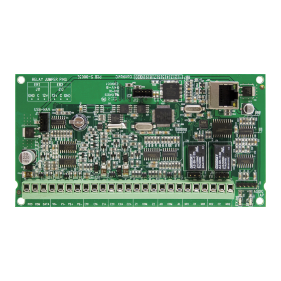
PCB Layout....................................................................................................................................... 6
Terminal Descriptions ..................................................................................................................... 6
FAQ - Frequently Asked Questions................................................................................................ 7
Enrolling the NX-595E...................................................................................................................... 9
Loading Factory Defaults (device 191) .......................................................................................... 9
Accessing the NX-595E - via the Web pages .............................................................................. 11
Feature Setup ................................................................................................................................. 24
Network Settings............................................................................................................................ 26
Output Settings .............................................................................................................................. 28
IP Reporting.................................................................................................................................... 30
Enable Remote Web Access ......................................................................................................... 31
Access via UltraSync App............................................................................................................. 33
Worksheets..................................................................................................................................... 35
System Status Messages Table.................................................................................................... 40
ComNav Installation Manual V3.1.0 UTC ONLY No Voice.doc
1
Advertisement
Table of Contents

Related Manuals for Interlogix NX-595E


Summary of Contents for Interlogix NX-595E
-
Page 1: Table Of Contents
Terminal Descriptions ........................6 FAQ - Frequently Asked Questions....................7 Enrolling the NX-595E........................9 Loading Factory Defaults (device 191) ..................9 Accessing the NX-595E - via the Web pages ................11 Feature Setup ..........................24 Network Settings..........................26 Output Settings ..........................28 IP Reporting............................ -
Page 2: Introduction
PROVIDER FOR REPLACEMENT BATTERIES. Installation Note A level of TCP IP knowledge is required by the installer/s to set up some of the NX-595E functionality. Hills Holdings limits it support to NX-595E setup only, and is unable to offer further assistance on your clients DSL modem, Router, firewall or any other 3 party software. - Page 3 THE ABILITY OF INTEROGIX’S PRODUCTS, SOFTWARE OR SERVICES TO WORK PROPERLY DEPENDS ON A NUMBER OF PRODUCTS AND SERVICES MADE AVAILABLE BY THIRD PARTIES OVER WHICH INTERLOGIX HAS NO CONTROL AND FOR WHICH INTERLOGIX SHALL NOT BE RESPONSIBLE INCLUDING, BUT NOT LIMITED TO, INTERNET, CELLULAR AND LANDLINE CONNECTIVITY;...
- Page 4 THE ABOVE EXCLUSION MAY NOT APPLY TO YOU. YOU MAY ALSO HAVE OTHER LEGAL RIGHTS THAT VARY FROM STATE TO STATE. INTERLOGIX DOES NOT MAKE ANY CLAIMS OR WARRANTIES TO YOU OF ANY KIND REGARDING ANY PRODUCT, SOFTWARE OR SERVICE’S POTENTIAL, ABILITY, OR EFFECTIVENESS TO DETECT, MINIMIZE, OR IN ANYWAY PREVENT DEATH, PERSONAL INJURY, PROPERTY DAMAGE, OR LOSS OF ANY KIND WHATSOEVER.
-
Page 5: Installing The Nx-595E Into The Enclosure
Installing The NX-595E Into The Enclosure Inside the NetworX enclosure, several 2-hole insertion points have been constructed. This allows for either vertical or horizontal placement of the modules. Notice that the insertion points have two sizes of holes - a larger hole and a smaller hole. -
Page 6: Wiring The Nx-595E
Wiring The NX-595E Remove all power to the NetworX security system and connect NX-595E terminals POS, COM & DATA to the NetworX bus. *Connect J14 (RJ45) to available network port via a patch cable. *Connect zone inputs if required 3.3K Single EOL’s 3.7K Lower zone EOL’s (when zone doubled) -
Page 7: Faq - Frequently Asked Questions
Do I need an email server? You do not need an email account to send emails as the new NX-595E will send emails using a secure cloud service. This is automatically configured and you only need to specify the destination email address(es). - Page 8 Check that the emails are not being captured in your SPAM folder or blocked by a firewall. Check the email address is correct. Check that the event is ticked in the NX-595E settings. Check that you are receiving other emails. Check that the relevant reporting options are enabled in the panel programming.
-
Page 9: Enrolling The Nx-595E
Loading Factory Defaults (device 191) The NX-595E is automatically set to device number 191, and programming is carried out like all other NetworX modules. The following examples show how to access the programming of the NX- 595E via a standard keypad or a VoiceNav keypad. The NX-595E will require defaulting the first time it is accessed by entering [9][1][0][#] or [9][1][0] [ENTER] depending on the keypad type. - Page 10 Touch menu to go back. [ 9 ][ 1 ][ 0 ] Defaults the device, Note: only required once [ENTER] You are now ready to begin NX-595E programming [MENU] Moves back to step 4, select a device number [MENU] Moves back to step 3, Advanced system configuration selection.
-
Page 11: Accessing The Nx-595E - Via The Web Pages
Feature 19 – IP Feature Settings Enable option 1 to turn on DHCP which will allow your router to assign the NX-595E and IP address automatically. Disable this option to manually assign an IP address. Enable option 2 to force SSL connections, turn off to allow either standard or SSL connections. - Page 12 ComNav Installation Manual V3.1.0 UTC ONLY No Voice.doc...
- Page 13 Sign in Page When successfully connected, the NX-595E will display the “Sign in Page”. Enter the correct username/password combination to login. Default Installer Username: installer (username is case sensitive) Default Password: 9713 (the NetworX panel Go To Program code) The default installer name can be changed on the Feature Setup menu after you have logged in.
- Page 14 Main Menu – Installer Code The screen shot above shows the NX-595E’s menu when accessed via the default installer code when the main panel is in program mode. Feature Setup, Network Settings, Output Settings, and IP Reporting will only be displayed when the main panel is in program mode.
- Page 15 Main Menu – Installer Code with Master Authority The screen shot above shows the NX-595E’s complete menu when accessed in program mode via an installer code that has been modified to allow master access. Refer to your alarm panel programming manual for instructions on enabling the “Go To Program Code”...
- Page 16 Main Menu – Master Code Installer menus will be hidden when accessed by a user with master code. Main Menu – Standard User Code Menus for changing system settings will also be hidden when accessed by standard users. ComNav Installation Manual V3.1.0 UTC ONLY No Voice.doc...
- Page 17 Status and Area Control Area Colour Green Area is active, and all zones are secure Yellow Area is armed in the stay mode Area is armed in the away mode Blue System condition present Grey Area not ready, zone(s) open Up to 8 active areas can be displayed, and control can be individual or as a group.
- Page 18 Zones From the Zones menu you can view zone status and bypass zones. Maximum zone count for the specific NetworX panel will be displayed. The two extra zones on the NX-959E will not be displayed here. ComNav Installation Manual V3.1.0 UTC ONLY No Voice.doc...
- Page 19 Output Control If you have outputs connected, you can control them from the Output Control menu. ComNav Installation Manual V3.1.0 UTC ONLY No Voice.doc...
- Page 20 History Current System faults will be displayed in the Arm/Disarm page and the system’s past 185 event log can be accessed via the History menu. Oldest – Will display the last event stored in the internal event log. Prev – (Previous) will display the previous consecutive event from the internal event log to what is currently displayed.
- Page 21 User Areas – select the areas the user will be allowed to access and control. You must create a user name for your customer to enable them to login to the NX-595E. Write the user name and PIN code on the back page of the User Manual. Enable the Master User Authority to permit them to create additional users.
- Page 22 The installer account is for installer access only and allows panel programming. It is not recommended to provide this code to the end-user. ComNav Installation Manual V3.1.0 UTC ONLY No Voice.doc...
- Page 23 Email addresses 1, 2 and 3: Enter up to three the email address, which will receive emails when the selected event(s) are activated. Return Address: This will appear in emails from your NX-595E as the return email address. Email Reporting – examples...
-
Page 24: Feature Setup
Zone-doubling - this feature will allow the two onboard zones to double to four zones. Lower Higher Zone Zone Zone Single EOL Zone Doubled EOL’s Starting Zone - Used to enter the starting zone number of the additional zones on the NX-595E. Data Zones Data Zones Data Zones Data... - Page 25 DST Start / End week – Selects which Sunday daylight savings begins and ends for the particular installation region. Firmware, Hardware, Web Version, Voice, and Language - Displays the current versions loaded on the connected NX-595E. ComNav Installation Manual V3.1.0 UTC ONLY No Voice.doc...
-
Page 26: Network Settings
The “ping” command is always functional whilst the NX-595E is in program mode and is defaulted to NOT operate whilst the NX-595E is in the normal run mode. Enable this option to allow the NX-595E to respond to "ping" commands in normal operation. For security reasons it is recommended this option remain disabled during normal operation. - Page 27 NTP Server Time Updates : The NX-595E will check its internal and use the internet to compare it against GMT time. This is done every 15min and will update itself if the variance is greater than 3 minutes. Enable Web Access: This enables the app and automatic email configuration.
-
Page 28: Output Settings
Output Settings The two onboard relays can be controlled through various system events or manually controlled by a user from the web page or smartphone app. ComNav Installation Manual V3.1.0 UTC ONLY No Voice.doc... - Page 29 Note: From the activation event drop down list “Output 1 Trigger” and ”Output 2 Trigger” are fixed X10 module commands 0 and 1. This allows you to send an X10 module command 0 or 1 remotely by using Menu 4-Output Control on the NX-595E. Drop down Event...
-
Page 30: Ip Reporting
IP Reporting Serial Number - The serial number of the NX-595E. Receiver format - Select the reporting format to match the IP receiver. Contact the control room for the correct settings. Use Control As Backup - Use the main panel dialler as backup if IP reporting fails... -
Page 31: Enable Remote Web Access
Look for the serial number label on the back of the NX-595E PCB WRITE THIS SERIAL NUMBER ON THE BACK OF THE USER MANUAL Find the IP address of your NX-595E. This is stored in Device 191, Feature 21 Enter the IP address into a web browser then login:... - Page 32 ComNav Installation Manual V3.1.0 UTC ONLY No Voice.doc...
-
Page 33: Access Via Ultrasync App
Enter the details of your security system – this should be on the back of this manual, if not please contact your service provider or builder for assistance The serial number is printed on the back of the NX-595E unit. Alternatively login to NX- 595E Web Server and go to IP Reporting to view it. - Page 34 Check all access codes are correct (serial number, Web Access Passcode is not 00000000, username, PIN) Check you can connect to the NX-595E web server from a web browser on your mobile device, while it is connected to the same network. ComNav Installation Manual V3.1.0 UTC ONLY No Voice.doc...
-
Page 35: Worksheets
Worksheets Feature 0 – RESERVED Feature 1 - NX-595E Features Option 1 is used to set the zone-doubling feature. This feature will allow the two onboard zones to double to four zones. Please refer to feature 18 for starting zone number. If this feature is unselected, both onboard zones remain as single end of line zones and require 3K3 resistors. - Page 36 Feature 18 - Zone Starting Number Feature 18 is used to enter the starting zone number of the additional zones on the NX-595E. The two zones can also be zone doubled, please refer to feature 1 to enable the zone doubling feature.
- Page 37 Configuration Server's web pages via FTP. Normally disabled. Enable Ping in the run mode: The “ping” command is always functional whilst the NX-595E is in program mode and is defaulted to NOT operate whilst the NX-595E is in the normal run mode.
- Page 38 (Internet). Segments 1 - 4 Feature 21 - NX-595E IP Address The 4 segments in feature 21 are used to set the IP address of the NX-595E so as it can be identified on the network. Segments 1 - 4 Feature 22 - Subnet Mask The 4 segments in feature 22 are used to set the Subnet mask.
- Page 39 Feature 26 - UHS Client reporting selections Event selection for UHS client reporting Segment 1 Alarms Alarm Restores Open / Close (security system disarmed = Open, security system armed = close. Zone Bypass and restores Zone Trouble and restores Power Trouble and restores (AC Failure or Low Battery) Tamper and restores (Zones, Box, Keypad and Zone Activity Monitor) Test Reports Segment 2...
-
Page 40: System Status Messages Table
System Status Messages Table Zone Number / Zone Name In alarm – This zone has triggered a system alarm condition Is bypassed – This zone is isolated (disabled) and will not activate an alarm Chime is set – This zone is part of the chime group Is not secure –... - Page 41 Expander Low battery – A remote power supply’s back up battery requires charging AC power fail – A remote power supply has lost its electricity power Box tamper – An expanders cabinet tamper input has activated Keypad Fire alarm – A fire alarm has been activated at the keypad Panic –...
Need help?
Do you have a question about the NX-595E and is the answer not in the manual?
Questions and answers