Advertisement
Quick Links
5
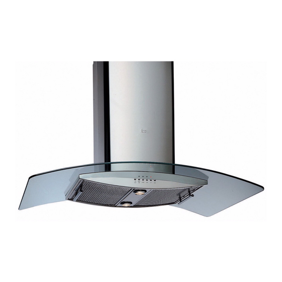
DECORATIVE HOODS
When fitting a decorative hood, there are a number of important factors to bear in mind. These
include:
Before installing the hood, check that there are is no aesthetic damage, such as scratches
or dents before you procede.
Check that all the technical information appearing on the specification plate corresponds to
the characteristics of the mains electrical supply in question (voltage and frequency).
Respect at all times the local regulations referring to electrical installation and evacuation of
gases.
The appliance should be connected to the mains supply via a suitable omnipolar switch
with a 3 mm miminum gap between contacts.
Do not connect the appliance to ducts used for the evacuation of gases of a non-electrical
nature, such as boilers, chimneys etc.
Do not start up the appliance if the mains cable or control panel appear to be damaged in
any way.
Once the apparatus has been fitted, ensure that the mains cable does not come into
contact with sharp metal edges.
Minimum distances between the hob and hood should be strictly observed: 60cm for
electric hobs 70 cm for gas and mixed hobs.
For optimum performance, theexit duct should not exceed 4 metres in length, nor have
more than two 90º bends, and its diameter should be at least 120 mm.
'
I
NSTALLER
43
M
S
ANUAL
Code Nº: PRM-00-0001
Revised / Date: 2006
Page Nº: 43 of 95
Advertisement


Need help?
Do you have a question about the ISLA and is the answer not in the manual?
Questions and answers
Hi need a replacement 40468432 lamp assembly