Chapters
Table of Contents
Troubleshooting

Subscribe to Our Youtube Channel
Related Manuals for NEC MultiSync LCD1700NX A


Summary of Contents for NEC MultiSync LCD1700NX A
-
Page 1: Service Manual
PART NO. 599910638 SERVICE MANUAL MultiSync LCD1700NX COLOR MONITOR MODELS LCD1700NX (A)/-BK(A)/(B)/-BK(B) NEC-MITSUBISHI ELECTRIC VISUAL SYSTEMS CORPORATION APRIL 2002 200304 08ED1AAD 08ED2AAD 08ED1ABD 08ED2ABD... - Page 2 WARNING The SERVICE PERSONNEL should have the appropriate technical training, knowledge and experience necessary to: • Be familiar with specialized test equipment, and • Be careful to follow all safety procedures to minimize danger to themselves and their coworkers. To avoid electrical shocks, this equipment should be used with an appropriate power cord. This equipment utilized a micro-gap power switch.
- Page 3 CONTENTS Page No. USER'S MANUAL ------------------------------------------------------------------- 1-1 SERIAL NUMBER INFORMATION --------------------------------------------- 2-1 DISASSEMBLY ----------------------------------------------------------------------- 3-1 ADJUSTMENT PROCEDURES -------------------------------------------------- 4-1 INSPECTION --------------------------------------------------------------------------- 5-1 TROUBLE SHOOTING ------------------------------------------------------------- 6-1 CIRCUIT DESCRIPTION ----------------------------------------------------------- 7-1 REPLACEMENT PARTS LIST --------------------------------------------------- 8-1 BLOCK DIAGRAM ------------------------------------------------------------------- 9-1 SCHEMATIC DIAGRAMS -------------------------------------------------------- 10-1 PACKING SPECIFICATION ------------------------------------------------------ 11-1...
-
Page 4: User's Manual
User's Manual 1. A Version 1700NX... -
Page 5: Table Of Contents
TABLE OF CONTENTS Warning ----------------------------------------------------------------------------- 1 FCC compliance statement ------------------------------------------------------- 1 DOC compliance notice ---------------------------------------------------------- 2 DECLARATION OF CONFORMITY ----------------------------------------- 2 Introduction ------------------------------------------------------------------------ 3 Features ----------------------------------------------------------------------------- 3 Unpacking -------------------------------------------------------------------------- 4 Screen position adjustment ------------------------------------------------------- 5 Connecting the power cord ------------------------------------------------------- 5 Recomended Use ------------------------------------------------------------------ 6 DDC --------------------------------------------------------------------------------- 8 Installation -------------------------------------------------------------------------- 9... -
Page 6: Warning
MultiSync LCD1700NX WARNING TO PREVENT FIRE OR SHOCK HAZARDS, DO NOT EXPOSE THIS UNIT TO RAIN OR MOISTURE. ALSO, DO NOT USE THIS UNIT'S POLARIZED PLUG WITH AN EXTENSION CORD RECEPTACLE OR OTHER OUTLETS UNLESS THE PRONGS CAN BE FULLY INSERTED. REFRAIN FROM OPENING THE CABINET AS THERE ARE HIGH VOLTAGE COMPONENTS INSIDE. -
Page 7: Doc Compliance Notice
MultiSync LCD1700NX We hereby declare that the equipment specified above conforms to the technical standards as specified in the FCC Rules. Windows is a registered trademark of Microsoft Corporation. NEC is a registered trademark of NEC ® Corporation. E is a U.S. registered trademark. All other brands and product names are trademarks NERGY or registered trademarks of their respective owners. -
Page 8: Introduction
MultiSync LCD1700NX INTRODUCTION ® ™ Congratulations for purchasing the MultiSync LCD1700NX , a high performance 17- inch color TFT LCD monitor. The MultiSync LCD1700NX monitor provides flicker-free and color images at optional resolutions. Through this user guide, we will introduce you step-by-step all the features, functions and technical specifications of the LCD monitor. -
Page 9: Unpacking
User’s Guide LCD Monitor Power Cord 1700NX AC Adapter (LSE9901B1970) Video Signal Cable (D-Sub) User’s Manual... -
Page 10: Screen Position Adjustment
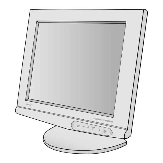
MultiSync LCD1700NX SCREEN POSITION ADJUSTMENT In order to optimize the best viewing position, you can adjust the tilt of the monitor by using both of your hands to hold the edges of the monitor as shown in the figure below. The monitor can be adjusted to 30 degrees up or 5 degrees down as indicated by arrow below. - Page 11 User’s Guide Recommended Use Safety Precautions and Maintenance FOR OPTIMUM PERFORMANCE, PLEASE NOTE THE FOLLOWING WHEN SETTING UP AND USING THE MULTISYNC ® LCD COLOR MONITOR: • DO NOT OPEN THE MONITOR. There are no user serviceable parts inside and opening or removing covers may expose you to dangerous shock hazards or other risks.
- Page 12 Do not use primary color blue on a dark background, as it is difficult to see and may produce eye fatigue to insufficient contrast For more detailed information on setting up a healthy work environment, call NEC- Mitsubishi Electronics Display of America at (800) 632-4662, NEC FastFacts ™...
- Page 13 User’s Guide ™ To make your installation easier, the monitor is able to Plug and Play with your system if your system also supports DDC protocol. The DDC (Display Data Channel) is a communication protocol through which the monitor automatically informs the host system about its capabilities, for example, supported resolutions and corresponding timing.
-
Page 14: Installation
MultiSync LCD1700NX INSTALLATION To install the monitor to your host system, please follow the steps as given below: Steps 1. Open the connector cover first. 2. And then open the cable cover. 3. Connect Video Cable a. Make sure both the monitor and computer are powered-OFF. b. -
Page 15: User Controls
User’s Guide USER CONTROLS DVI/D-SUB Front Panel Controls 1. Power Switch : To turn ON or OFF the power. 2. Power LED : Lights up to indicate the power is turned ON. 3. + : To increase the value of the parameter in the OSD, which have been selected for adjustment. -
Page 16: Standard Osd Operation
MultiSync LCD1700NX Standard OSD Operation 1. Press any front panel key to activate the OSD menu. 2. Use Select Up or Down keys to move up or down through the menu. The parameter will be highlighted when selected. 3. Then use + or - to increase or decrease the value of the parameter, or make selection between different options. - Page 17 User’s Guide Icon Item Function Description LANGUAGE Select among English, French, Italian, Deutsch and Spanish. RECALL To return the monitor to its default settings. DEFALTS OSD TIMEOUT The OSD menu will stay as long as it is in use. In the OSD TIMEOUT menu you can select how long the monitor waits after the last touch of a button to shut off the OSD menu.
-
Page 18: Troubleshooting
MultiSync LCD1700NX TROUBLESHOOTING Before sending your LCD monitor for servicing, please check the troubleshooting list below to see if you can self-diagnose the problem. Problems Current Status Remedy No Picture LED ON • Using OSD, adjust brightness and contrast to maximum or reset to their default settings. -
Page 19: Specification
–10°C to 60°C / 14°F to 140°F Humidity 10% to 85% Feet 0 to 40,000 Feet * NEC-Mitsubishi Electronics Display cites recommended resolution at 60 Hz for optimal display performance. ** Analog input only . All specifications are subject to change without notice. 1-16... -
Page 20: References
MultiSync LCD1700NX References • BBS (978) 742-8706 NEC-Mitsubishi Electronics Display of America Remote Bulletin Board System is an electronic service accessible with your system and a modem. Communication parameters are: 300/1200/2400/9600/14.4k/28.8k/33.6k bps, no parity, 8-data bits, 1 stop bit • Customer Service/... -
Page 21: Limited Warranty
Product may vary. Therefore, suitability of a Product for a specific purpose or application must be determined by consumer and is not warranted by NMD-A. For the name of your nearest authorized NEC-Mitsubishi Electronics Display service facility, contact NEC-Mitsubishi Electronics Display of America at 1-800-632-4662. -
Page 22: Proprietary Notice And Liability Disclaimer
Since implementation by customers of each product may vary, the suitability of specific product configurations and applications must be determined by the customer and is not warranted by NEC- Mitsubishi Electronics Display of America. -
Page 23: Tco'99
User’s Guide TCO’99 MultiSync LCD1700NX White Model Congratulations! You have just purchased a TCO’99 approved and la- beled product! Your choice has provided you with a product developed for professional use. Your purchase has also contributed to reducing the burden on the environment and also to the further development of environmentally adapted electronics products. - Page 24 MultiSync LCD1700NX Environmental Requirements Flame retardants Flame retardants are present in printed circuit boards, cables, wires, casings and housings. In turn, they delay the spread of fire. Up to thirty percent of the plastic in a computer casing can consist of flame retardant substances. Most flame retardants contain bromine or chloride and these are related to another group of environmental toxins, PCBs, which are suspected to give rise to severe health effects, including reproductive damage in fisheating birds and mammals, due to the bio-accumulative* processes.
-
Page 25: Tco'95
User’s Guide TCO’95 MultiSync LCD1700NX Black Model Congratulations! You have just purchased a TCO’95 approved and labeled product! Your choice has provided you with a product developed for pro- fessional use. Your purchase has also contributed to reducing the burden on the environment and also, to the further development of environmentally adapted electronics products. - Page 26 MultiSync LCD1700NX Environmental Requirements Brominated flame retardants Brominated flame retardants are present in printed circuit boards, cables, wires, casings and housings. In turn, they delay the spread of fire. Up to thirty percent of the plastic in a computer casing can consist of flame retardant substances. These are related to another group of envi- ronmental toxins, PCBs, which are suspected to give rise to similar harm, including reproductive damage in fisheating birds and mammals, due to the bio-accumulative* pro- cesses.
- Page 27 2. B Version MultiSync LCD1700NX User’s Manual Uživatelská pøíruèka Bedienerhandbuch Oäçãßåò ×ñÞóÞò Manual del usuario Manuel Utilisateur Manuale utente Gebruikershandleiding Podrêcznik u¿ytkownika Ðóêîâîäñòâî ïîëüçîâàòåëÿ Kullanécé Klavuzu 1-24...
- Page 28 FCC Rules. Windows is a registered trademark of Microsoft Corporation. NEC is a registered trademark of NEC Corporation. All other brands and product names are trademarks or registered trademarks of their respective owners.
- Page 29 MultiSync LCD1700NX 3 TCO’95 MultiSync LCD1700NX (black model) Congratulations! You have just purchased a TCO’95 approved and labeled product! Your choice has provided you with a product developed for professional use. Your purchase has also contributed to reducing the burden on the environment and also, to the further development of environmentally adapted electronics products.
- Page 30 4 User’s Manual TCO’95 – continued Lead** Lead can be found in picture tubes, display screens, solders and capacitors. Lead damages the nervous system and in higher doses, causes lead poisoning. TCO’95 requirement permits the inclusion of lead since no replacement has yet been developed. Cadmium** Cadmium is present in rechargeable batteries and in the colourgenerating layers of certain computer displays.
-
Page 31: Tco '99
MultiSync LCD1700NX 5 TCO ’99 MultiSync LCD1700NX (white model) Congratulations! You have just purchased a TCO ’99 approved and labeled product! Your choice has provided you with a product developed for profes- sional use. Your purchase has also contributed to reducing the burden on the environment and also to the further development of environmentally adapted electronics products. - Page 32 6 User’s Manual TCO’99 – continued Cadmium** Cadmium is present in rechargeable batteries and in the colourgenerating layers of certain computer displays. Cadmium damages the nervous system and is toxic in high doses. TCO ’99 requirement states that batteries, the colourgenerating layers of display screens and the electrical or electronics components must not contain any cadmium.
- Page 33 MultiSync LCD1700NX english – 1 LCD Monitor MultiSync LCD1700NX User’s Manual TABLE OF CONTENTS FCC Compliance Statement ........................Caution to the user ........................... DOC Compliance Notice .......................... DOC Avis de Conformation ........................DECLARATION OF CONFORMITY ......................TCO ‘95 ..............................TCO ‘99 ..............................Caution ..............................
-
Page 34: Caution
english – 2 User’s Manual Caution CAUTION: TO REDUCE THE RISK OF ELECTRIC SHOCK,MAKE SURE POWER CORD IS UNPLUGGED FROM WALL SOCKET. TO FULLY DISENGAGE THE POWER TO THE UNIT, PLEASE DISCONNECT THE POWER CORD FROM THE AC OUTLET. DO NOT REMOVE COVER (OR BACK). NO USER SERVICEABLE PARTS INSIDE. -
Page 35: Unpacking
MultiSync LCD1700NX english – 3 Unpacking Please check the following items are present when you unpack the box, and save the packing materials in case you will need to ship or transport the monitor in future. MultiSync LCD1700NX 1700NX • •... -
Page 36: Installation
english – 4 User’s Manual Installation To install the monitor to your host system, please follow the steps as given below: Steps 1. Open the connector cover first. 2. And then open the cable cover. 3. Connect Video Cable a. Make sure both the monitor and computer are powered-OFF. b. -
Page 37: User Controls
MultiSync LCD1700NX english – 5 User Controls AUTO DVI/D-SUB MENU Front Panel Controls 1. Power Switch To turn ON or OFF the power. 2. Power LED Lights up to indicate the power is turned ON. 3. + To increase the value of the parameter in the OSD, which have been selected for adjustment. -
Page 38: Osd Function Description
english – 6 User’s Manual OSD Function Description r i f ” - “ “ r ” + " ” + ” - “ t l u “ ” + l l i y l l A “ ” n “... -
Page 39: Osd Messages
MultiSync LCD1700NX english – 7 OSD Function Description – continued s i l a t I a i l t i n s t i t i n s t i t i s y l l " " + l l i "... -
Page 40: Recommended Use
english – 8 User’s Manual Recommended Use Safety Precautions and Maintenance FOR OPTIMUM PERFORMANCE, PLEASE NOTE THE FOLLOWING WHEN SETTING UP AND USING THE MULTISYNC LCD COLOR MONITOR: • DO NOT OPEN THE MONITOR. There are no user serviceable parts inside and opening or removing covers may expose you to dangerous shock hazards or other risks. - Page 41 MultiSync LCD1700NX english – 9 Recommended Use – continued CORRECT PLACEMENT AND ADJUSTMENT OF THE MONITOR CAN REDUCE EYE, SHOULDER AND NECK FATIGUE. CHECK THE FOLLOWING WHEN YOU POSITION THE MONITOR. • For optimum performance, allow 20 minutes for warm-up. •...
-
Page 42: Troubleshooting
MultiSync LCD1700NX is in compliance with Council Directive 73/23/EEC: – EN 60950 Council Directive 89/336/EEC: – EN 55022 – EN 61000-3-2 – EN 61000-3-3 – EN 55024 and marked with NEC-Mitsubishi Electric Visual Systems Corporation 4-13-23, Shibaura, Minato-Ku Tokyo 108-0023, JAPAN 1-39... -
Page 43: Specifications
° ° F ° F ° y t i i t l * NEC-Mitsubishi Electronics Display cites recommended resolution at 60 Hz for optimal display performance. ** Analog input only All specifications are subject to change without notice. 1-40... -
Page 44: Serial Number Information
Serial Number Information Refer to the serial number information shown below. EX.) SERIAL NUMBER LABEL Model Name : LCD1700NX LCD1700NX-BK SERIAL NO. : g g g g g g g g g Manufactured Year : ( Last digit ) Manufactured Month : January to September 1 to October... - Page 45 DISASSEMBLY g Before you disassemble the set, turn off power and pull out the power plug. g Use the proper screwdriver. If oversize or undersize screwdriver is used, screws may be damaged. g Assembly is the opposite process of disassembly. CABINET SYMBOL CODE(Lite-on)
- Page 46 CABINET SYMBOL CODE(Lite-on) CODE(NMV) DESCRIPTION COLOR 7737602659-0A 79PL2086 REAR COVER ASS’Y-NMV-U170 White 7737602661-0A 79PL2153 REAR COVER ASS’Y-NMV-U170 Black 7150240162-0A SCREW M4*16 White 7150240163-0A SCREW M4*16 Black...
- Page 47 SYMBOL CODE(Lite-on) CODE(NMV) DESCRIPTION 7150130041-0A SCREW M3*4 7748706510-0C SHIELD-CHASSIS CABINET SYMBOL CODE(Lite-on) CODE(NMV) DESCRIPTION COLOR 7140130121 SCREW M3*12 7737507302-0A 79PL2084 FRONT COVER ASS’Y-NMV-U17 White 7737507303-0A 79PL2152 FRONT COVER ASS’Y-NMV-U17 Black 7140130101 SCREW M3*10 5113800014 79PL2090 FUNCTION KEY BD P601...
- Page 48 SYMBOL CODE(Lite-on) CODE(NMV) DESCRIPTION 7110430081 SCREW M3*8 7740200890 SPECIAL(HEX) 5113300109 79PL2089 INTERFACE BD P307 P302 P308 SYMBOL CODE(Lite-on) CODE(NMV) DESCRIPTION 7110430081 SCREW M3*8 6716009410 79PL2085 INVERTER-DC-AC 19V-TAD585...
- Page 49 SYMBOL CODE(Lite-on) CODE(NMV) DESCRIPTION 7110230121 SCREW M3*12 6876003010 ALUMINIUM TAP-W20XL0340X30M-LU 6876000912 ALUMINIUM TAP-W20XL0090X30M-LU 6711120170-01 79PL2117 HARNESS—12P/9P-340mm-CG170-00 SYMBOL CODE(Lite-on) CODE(NMV) DESCRIPTION 6711300030-03 79PL2118 HARNESS—30P-190mm-20276#28(MO 6814002700 3A684028 LCD TX43D15VC0CAD...
- Page 50 CABINET SYMBOL CODE(Lite-on) CODE(NMV) DESCRIPTION COLOR 7738000290-0A HINGE-R 7738000280-0A HINGE-L 7742607742-0B 79PL2142 COVER-ARM FRONT-NMV-U170A White 7742607743-0B 79PL2169 COVER-ARM FRONT-NMV-U170A Black 7742607766-0A CABLE SUPPORT White 7742607767-0A CABLE SUPPORT Black 7737801101-0A BRACKET-STAND BASE ASS’Y 7737704456-0A 79PL2088 BASE ASS’Y-NMV-U170ATA-J White 7737704457-0A 79PL2170 BASE ASS’Y-NMV-U170ATA-JU Black...
- Page 51 ADJUSTMENT PROCEDURES TABLE OF CONTENTS Page 1. Application ----------------------------------------------------------------------------------------------------------------- 4-2 2. Basic Operation ---------------------------------------------------------------------------------------------------------- 4-2 2.1 General Conditions ------------------------------------------------------------------------------------------------- 4-2 2.2 Aging ------------------------------------------------------------------------------------------------------------------- 4-2 3. Adjustment Mode Setting ---------------------------------------------------------------------------------------------- 4-2 3.1 Power SW Closure ------------------------------------------------------------------------------------------------- 4-2 3.2 Factory Mode Description ----------------------------------------------------------------------------------------- 4-3 3.3 Adjustments Method ----------------------------------------------------------------------------------------------- 4-5 3.3.1 Factory Mode Access ---------------------------------------------------------------------------------------- 4-5 3.3.2 Factory Preset -------------------------------------------------------------------------------------------------- 4-5...
-
Page 52: Application
1. Application This specification should be applied to the adjustment of the LCD1700NX set. 2. Basic Operation 2.1 General Conditions Unless otherwise specified, adjustments should be carried out under the following conditions: 1) Power source voltage: AC 100 - 120V @ 1.5A, AC 220 – 240V @ 0.75A 2) Equipment to be used: Equipment that can generate an output of the adjusted VG-829 unit or equivalent 3) Connections: Connections are made to the D-Sub connector of the unit under inspection by means of the connector that can carry each output of the VG-829. -
Page 53: Factory Mode Description
3.2 Factory Mode Description How to enter the factory mode Pressing the [MENU] key and [ + (DVI/D-SUB)] key, press the power key from ON → OFF simultaneously, then press [MENU] key in order to obtain a display of the [Factory Mode] screen. How to close the factory mode Factory mode is closed by turning OFF →... - Page 54 Page 2 NMV1700NX 1 2 3 4 5 HOURS RUNNING 00060H45M 00119H08M In this page, it is possible to check the total user’s operation time. HOURS RUNNING (Total Operation Time) The time (hours and minutes) is displayed for the POWER ON mode and the OFF mode (power saving mode).
- Page 55 Page 4 NMV1700NX 1 2 3 4 5 VERSION F012 02/04/17 FACTORY PRESET In this page, it is possible to confirm the firmware version, and make factory preset. Version The firmware version is displayed. Factory Preset When the [ − (AUTO)] key or [ + (DVI/D-SUB)] key is pressed, it becomes possible to reset all the functions (HOURS RUNNING, AUTO ADJUST CONT and AUTO INFORMATION) to their initial values.
-
Page 56: Adjustments Method
3.3 Adjustments Method 3.3.1 Factory Mode Access (1) Enter a window pattern input of Input Signal 15 (VESA 1280 × 1024 (75Hz)). (2) Pressing the [MENU] key and [ + (DVI/D-SUB)] key, press the power key from ON → OFF simultaneously, then press [MENU] key in order to obtain a display of the [Factory Mode] screen. - Page 57 3.3.3 Auto Balance Adjustment (1) Select page 1. (2) Enter a window pattern input of Input Signal 15 (VESA 1280 × 1024 (75Hz)). (3) Press the [6] key and move the cursor to [AUTO BALANCE]. (4) Press the [ − (AUTO)] key or [ + (DVI/D-SUB)] key to execute the adjustment of Auto Balance. NMV1700NX 1 2 3 4 5 AUTO BALANCE...
-
Page 58: Ex-Factory Setting
3.4 Ex-Factory Setting Power Button: OFF Brightness: Preset 80% Contrast: Preset 50% Analog Contrast: Preset 50% Color Temperature: NATIVE Left/Right: Optimal value for the signals, which is stated in the VESA standard. Down/Up: Optimal value for the signals, which is stated in the VESA standard. H.Size: Optimal value for the signals, which is stated in the VESA standard. -
Page 59: Preset Signal Timing Sheet
4. Preset Signal Timing Sheet Preset No. Item Abbreviation VGA 720 x 400 70Hz VGA 640 x 480 60Hz Pixel frequency 28.322MHz 25.175MHz Horizontal frequency 31.47kHz 31.47kHz Line time total 900CLK 800CLK 31.78µs 31.78µs Horizontal active display 720CLK 640CLK 25.42µs 25.42µs Horizontal sync pulse 108CLK... - Page 60 Preset No. Item Abbreviation VESA 640 x 480 75Hz VESA 800 x 600 56Hz Pixel frequency 31.500MHz 36.000MHz Horizontal frequency 37.50kHz 35.16kHz Line time total 840CLK 1024CLK 26.67µs 28.44µs Horizontal active display 640CLK 800CLK 20.32µs 22.22µs Horizontal sync pulse 64CLK 72CLK 2.03µs 2.00µs...
- Page 61 Preset No. Item Abbreviation VESA 1024 x 768 60Hz VESA 1024 x 768 70Hz Pixel frequency 65.000MHz 75.000MHz Horizontal frequency 48.36kHz 56.48kHz Line time total 1344CLK 1328CLK 20.68µs 17.71µs Horizontal active display 1024CLK 1024CLK 15.75µs 13.65µs Horizontal sync pulse 136CLK 136CLK 2.09µs 1.81µs...
- Page 62 Preset No. Item Abbreviation VESA 1280 x 960 60Hz VESA 1152 x 900 60Hz Pixel frequency 108.00MHz 94.50MHz Horizontal frequency 60.00kHz 61.85kHz Line time total 1800CLK 1528CLK 16.67µs 16.17µs Horizontal active display 1280CLK 1152CLK 11.85µs 12.19µs Horizontal sync pulse 112CLK 128CLK 1.04µs 1.35µs...
- Page 63 INSPECTION TABLE OF CONTENTS Page 1. Inspection of PLUG & PLAY Communication ---------------------------------------------------------- 5-2 1.1 System Connection ----------------------------------------------------------------------------------------- 5-2 1.2 Input Signal --------------------------------------------------------------------------------------------------- 5-3 1.3 Program ------------------------------------------------------------------------------------------------------- 5-3 1.4 Operation ------------------------------------------------------------------------------------------------------ 5-3 1.4.1 D-Sub (Analog) EDID Data Write ------------------------------------------------------------------ 5-3 1.4.2 DVI-D (Digital) EDID Data Write ------------------------------------------------------------------- 5-6 1.5 EDID Data File ----------------------------------------------------------------------------------------------- 5-7 2.
-
Page 64: Inspection Of Plug & Play Communication
1. Inspection of PLUG & PLAY Communication 1.1 System Connection This system should be connected as shown below. Fig 1.1.1 D-SUB connector connection (Part No. 599910604) Fig 1.1.2 DVI connector connection DDC Communication I/F BOARD... -
Page 65: Input Signal
1.2 Input Signal Horizontal synchronization frequency : Not specified. Vertical synchronization frequency : Not specified. 1.3 Program Service tool Ver. 3.14 (Parameter ver. 2.0-S9) (Part No. 599910612) 1.4 Operation 1.4.1 D-Sub (Analog) EDID Data Write 1) Connect the EDID data writing unit with jigs, etc. (Refer to a D-SUB connector connection figure) 2) Copy all the files of the service tool Ver. - Page 66 5) When the screen as shown below appears, adjust the cursor to [LCD1700NX-ANALOG] and make a double click. 6) When the screen as shown below appears, give a check to [EDID_READ] and press the [OK] button.
- Page 67 7) When the screen as shown below appears, confirm that the correct data are displayed in the columns of EDID DATA CONTENTS and Serial information. If all the displayed data are [FF] or the like, or if the serial number is different from that of the corresponding unit, then EDID data writing should be carried out.
-
Page 68: Dvi-D (Digital) Edid Data Write
10) When the [WRITE EDID] button is pressed, writing of the EDID data only is carried out. Upon the completion of correct writing, a display of [EDID Monitor Write OK] is presented in the column of [STATUS]. 1.4.2 DVI-D (Digital) EDID Data Write 1) Connect the EDID data writing unit with jigs, etc. -
Page 69: Edid Data File
1.5 EDID Data File EDID Data : LCD1700NX_A.EDI (ANALOG) EDID Data : LCD1700NX_D.EDI (DIGITAL) Week of manufacture = Month of manufacture × 4 Note 1: address 10h Note 2: address 11h Year of manufacture - 1990 Note 3: address 71h ~ 7Dh Serial Number (ASCII coded) If less than 13 char, terminate with 0Ah and fill the rests with 20h. -
Page 70: External Inspection On The Lcd Module
2. External inspection on the LCD module 2.1 Inspection Method 2.1.1 Environmental a) Temperature: 20 degree b) Ambient light: About 150 lx and non-directive when operating inspection. About 1000 lx and non-directive when non-operating inspection. c) Back light: When non-operating inspection, back light should be off. 2.1.2 Viewing Zone Inspection view a) The figure shows the correspondence between eyes (of inspector) -
Page 71: Dot Defect
2.2 Dot Defect This criteria is based on ISO-13406-2 Pixel Faults Class II Inspection Criteria Remark Green Max. 4 1 dot fault Total Max. 7 Bright dots Adjacent two bright dots Max. 3 Note 1 Three or more continuous Not Allowed Note 2 Dot defects 1 dot... - Page 72 Note 2. Horizontally, Vertically or combined adjacent 3 dots (separately bright dots and dark dots) Count as adjacent 3 dots Do not count as adjacent 3 dots Note 3. Count as 1 cluster: Two or more sub-pixels with fault of No. 5 within 5x5 pixels 3 or below. 5x5 pixels Dot Defect (5) 1 Cluster...
-
Page 73: Polarizer Defects
2.3 Polarizer Defects Display Items Criteria W = 0.02 or less L = Pass Pass L = 40 or less Linear Scratch W = 0.04 or less W: Width (mm) L = 40 over Not Allowed L: Length (mm) L = 20 or less Turn ON W = 0.08 over L = 20 over... -
Page 74: Line Defect
2.5 Line Defect All kinds of line defects such as vertical, horizontal or cross are not allowed. 2.6 Bezel Appearance Scratches, minor bents, stains, particles on the Bezel frame are not considered as a defect. 2.7 Display Tilt and Position Difference Any part of image must not be missed by the position difference or the display tilt. -
Page 75: Safety
3. Safety 3.1 Insulation Resistance The resistance of the insulation between the power terminal and the earth ground contact is more the 10M ohms while withstanding a voltage of 500Vdc. 3.2 Dielectric Strength There is no breakdown of the insulators or short circuits when applying an alternating potential of 1000Vac for a duration of 1(one) minute or 1500Vac for a duration of 2(two) second at 50Hz between the metallic chassis and the input power supply active and neutral terminals connected together. - Page 76 TROUBLE SHOOTING TABLE OF CONTENTS Page 1. No Display on Screen (Screen is Black, LED is Amber) -------------------------------------- 6-2 2. No Display on Screen (Screen is Black, LED is Green) --------------------------------------- 6-3 3. Checking the Back Light Unit ------------------------------------------------------------------------ 6-6 4.
-
Page 77: No Display On Screen (Screen Is Black, Led Is Amber)
1. No Display on Screen (Screen is Black, LED is Amber) Does OSM display when you push PROCEED button? When a signal isn't being Pressed "No OSM Display" section. input, it is indicated with "NO VIDEOINPUT". It is indicated with "OUT OF RANGE"... -
Page 78: No Display On Screen (Screen Is Black, Led Is Green)
2. No Display on Screen (Screen is Black, LED is Green) Is backlight lit? Refer "Checking the Backlight Unit" section Does computer output Check the video cable for failure. RGB video signals? Check the host for output signal with all black only. 1) Change pattern of video signal output on the host. - Page 79 Continue Check the 3.3 V power are supplied on I323, I330 pin 2. Check if the voltage on I323, I330 pin 3 is high (5Vdc). Failure point 1) Printed wire broke between I322 and I323, I330. 2) I322 failure. Failure point I323, I330 Failure Is a dot clock being output under the condition that a LCD module is connected...
- Page 80 Continue Check the data enable of positive polarity are output on RN314 pin 6. Failure point 1) I315 failure 2) Printed wire broke between I315 and RN314 pin 6. Check the data signal output on I315 R, G, B data pin. Failure point I315 failure Check I319, I320 all LVDS signal...
-
Page 81: Checking The Back Light Unit
3. Checking the Back Light Unit Is +19V supplied to F301 pin 1? Is connected AC adapters operating normally? Failure point Is +19V supplied to P308 pins 3, AC adapter needs to be 4 to inverter PWB? changed to a normally operating unit. -
Page 82: Abnormal Screen
4. Abnormal Screen Check the R, G, B video signal from computer input on D-Sub R, G, B connector. Failure point 1) No R, G and B video signal output from host computer. Check computer 2) Video signal cable disconnection. Check the R, G, B input signals on I315 pins E1, D2, C1 respectively that their level is 0.7Vp-p maximum. - Page 83 Continue Check the negative vertical sync pulse output to RN314 pin 7 from I315 pin F19 at TTL level. Failure point 1) Printed wire broke between I315 pin 73 and RN314 pin 7. 2) I315 failure. Check the positive DE pulse output to RN314 pin 6 from I315 pin F18 at TTL level.
- Page 84 Continue Check I319, I320 all LVDS signal pins. Failure point 1) I319, I320 failure. 2) Printed wire broke between I319, I320 and P307. Check SDRAM IC clk signal output to I318, I316, I317 pin 35 from I315 pin T3. Failure point 1) R396 open.
-
Page 85: No Osm Display
5. No OSM Display 5.1 No OSM Display Check the input of 3.3Vp-p pulse from I315 pin P3, P4, R1, R2, P2, P1. Failure point 1) Printed wire broke between I315 pin P3 and I302 pin 5. 2) Printed wire broke between I315 pin P4 and I302 pin 4. 3) Printed wire broke between I315 pin R1 and I302 pin 3. -
Page 86: Abnormal Plug And Play Operation
6. Abnormal plug and play operation Abnormal DDC2 Confirm the input of serial clock on I312 pin 6, I310 pin 6 synchronize SCL at TTL level. Failure point I310, I312 failure Failure point 1) The host machine isn’t communicating in DDC2 mode. 2) The video cable may have failed or may not have connections for DDC. -
Page 87: Checking The Sync Signal Interface Circuit
7. Checking the Sync Signal Interface Circuit 7.1 Checking the Horizontal Sync Pulse Control Circuit Check the horizontal sync signal on I315 pin L2 TTL level. Failure point 1) Video cable may have failed. 2) Printed wire broke between P304 pin 13 and I315 pin L2. 3) FB305, R329 open. -
Page 88: Checking The Ic Resolution Change Movement
8. Checking the IC Resolution Change Movement Is there +3.3V supply on I315 pins D13, D15, D16, E17, G17, J17, L17, N17, R17, U17, U15, U13, U12, U10, U8, U6, U5, T4, L4, B2, B6, B7, B8, B9, B11, C3, D3, E3, F2, F4, G1, G3, H1, J1 and J3? Proceed "Checking the DC/DC Converter Circuit"... -
Page 89: No Power On
9. No Power On Check +19V power is supplied from power adapter. Failure point AC adapter failure. Is LED turned on in amber momentarily when a power button is pushed ? Failure point Fuse failure. Process "Checking the CPU Operation" section. 6-14... -
Page 90: Checking The Dc/Dc Converter Circuit
10. Checking the DC/DC Converter Circuit Check if the 5V is output from I322 pin 2. Failure point Printed wire broke between I322 pin 1 and L314 pin 2. Check the output of 3.3V line voltage from I323 pin 2. Is the output FB335 being inputted to I315 pin 3? Failure point Printed wire broke between I323 pin 3 and output of FB335. -
Page 91: Checking The Cpu Operation
11. Checking the CPU Operation Is there +5.0V supply on I302 pin 44. Failure point Printed wire broke between output of FB331 and I302 power supply pin. Is 24MHz clock input to I302 pins 20 and 21 at TTL level? Failure point X301 failure. - Page 92 CIRCUIT DESCRIPTION TABLE OF CONTENTS Page 1. Power Supply --------------------------------------------------------------------------------------- 7-2 2. Video Input Circuit --------------------------------------------------------------------------------- 7-2 3. Definition Converter LSI Peripheral Circuit -------------------------------------------------- 7-2 4. System Reset, LED Control Circuit ------------------------------------------------------------ 7-2 4.1 System Reset ------------------------------------------------------------------------------------- 7-2 4.2 LED Control Circuit ------------------------------------------------------------------------------ 7-2 5.
-
Page 93: Power Supply
1. Power Supply (Circuit Diagram: Power PWB) 1.1 I322: DC-DC Converter A 5V power supply for LCD module, CPU, and logic is generated from the 19V source. 1.2 I323: 3-terminal Regulator A 3.3V power supply for Scaler IC I315, LVDS IC I319, I320 is generated from the 5V source. 1.3 I330: 3-terminal Regulator A 3.3V power supply for SDRAM IC I316, I317, I318 is generated from the 5V source. -
Page 94: E 2 Prom For Pnp
5. E PROM for PnP (Circuit Diagram: Interface PWB) 6. E PROM (Circuit Diagram: Interface PWB) Data transfer between I305 (AT24 C16) and CPU by the IIC bus SCL (pin 15) and SDA (pin 16) of I302. The data to be transferred to each device are stored in I305. I315 control data. - Page 95 Table 1 Table 2 the number of the lines, Vsync distinction H-freq Band Width Polarity Mode Resolution (KHz) (MHz) VGA 720 x 400 70Hz 31.47 28.322 VGA 640 x 480 60Hz 31.47 25.175 MAC 640 x 480 66Hz 32.24 VESA 640 x 480 72Hz 37.86 31.5 VESA 640 x 480 75Hz...
-
Page 96: User Control
7.3 User Control 7.3.1 Related Ports of I315 and I302 Pin Functions Port Pin No. Signal name Function Remarks GPI04 I315, M1 NENU EXIT/ENTER switch input ENTER/Withdraw from OSD 6 switch input DOWN GPI05 I315, L1 (6)key − 3 switch input GPI06 I315, G18 (3)key... -
Page 97: Power On Sequence
7.6 Power ON Sequence When the POWER switch is pressed, the POWER OFF signal is turned “H”. When this “H” potential is detected, the CPU begins to establish the respective power supplies according to the sequence shown below. POWER 85ms 520ms Panel_VCC 50ms... -
Page 98: List Of Cpu Pin Assignments
7.8 List of CPU Pin Assignments Port Pin No. Signal Name Initial Setting Function Remark P1.0 HDATA0 gm5020 4bit interface data P1.1 HDATA1 gm5020 4bit interface data P1.2 HDATA2 gm5020 4bit interface data P1.3 HDATA3 gm5020 4bit interface data P1.4 HCLK gm5020 4bit interface clock P1.5... - Page 99 REPLACEMENT PARTS LIST(For U.S.) The components specified for Model LCD1700NX(A) SYMBOL Part No for Lite-on DESCRIPTION *** ICS *** I301 6444006108 IC-M51953AFP-8P-SOP I302 6448018900 IC-CPU-SM89516C25J-44PIN- I305 6448016508 IC-EEPROM-24LC16B/SN-8P-S I306 6446006608 IC-TTL-74HCT573DT-20P-SMD I310 6448018208 IC 24LC02B 8PIN SOP MICRO I312 6448018208 IC 24LC02B 8PIN SOP MICRO I315 6444007608...
- Page 100 Part No for Lite-on SYMBOL DESCRIPTION D316 6414056038 DIODE ZNR RLZ TE-11 5.6B D317 6412001778 DIODE-MM4148-SMD-GOODARK D318 6414056038 DIODE ZNR RLZ TE-11 5.6B D319 6412001778 DIODE-MM4148-SMD-GOODARK D320 6414056038 DIODE ZNR RLZ TE-11 5.6B D321 6412001778 DIODE-MM4148-SMD-GOODARK D322 6412001778 DIODE-MM4148-SMD-GOODARK D323 6414056038 DIODE ZNR RLZ TE-11 5.6B D324...
- Page 101 Part No for Lite-on SYMBOL DESCRIPTION FB319 6881600308 BEAD CORE WB160808B121QNT FB321 6881800858 BEAD COREHB-1P4516-600T60 FB322 6881600308 BEAD CORE WB160808B121QNT FB323 6881600308 BEAD CORE WB160808B121QNT FB324 6881800858 BEAD COREHB-1P4516-600T60 FB325 6881200658 BEAD CORE HH-1M3216-121JT FB326 6881006200 BEAD CORE W4B RH FB327 6881006200 BEAD CORE W4B RH...
- Page 102 COVER-ARM FRONT-NMV-U170A B02R 7737704456-0A BASE ASS'Y-NMV-U170ATA-JU B02T 7742607706-0A COVER-ARM REAR-NMV-U170AT 7737507302-0A FRONT COVER ASS'Y-NMV-U17 *** PRINTED & PACKING MATERIALS *** B01L 7735425680-0A LABEL-MODEL LABEL-NEC--U1 7749205499-0A CARTON BOX LCD1700NX(A) 7749103000-0B CUSHION-FOAM-EPS-17LCD17" 7749001130-0A PLASTIC BAG 7749000200-0D PLASTIC BAG 7735425965-0A XTRA VIEW+ LCD1700NX(A) Y002...
- Page 103 Part No for Lite-on SYMBOL DESCRIPTION R339 6252750956 CHIP-R OHM 75 1/10W J R340 6252100056 CHIP-R OHM 100 1/10W J 06 R341 6252100056 CHIP-R OHM 100 1/10W J 06 R343 6252750956 CHIP-R OHM 75 1/10W J R344 6252100056 CHIP-R OHM 100 1/10W J 06 R345 6252100056 CHIP-R OHM 100 1/10W J 06...
- Page 104 Part No for Lite-on SYMBOL DESCRIPTION RN324 6264702818 FRN,OHM,47,1/16W,J,8P4R RN325 6264702818 FRN,OHM,47,1/16W,J,8P4R RN326 6264702818 FRN,OHM,47,1/16W,J,8P4R *** CAPACITORS *** C301 6311247009 ALU 47UF 16V 85C SMD C302 6373410486 C,MC UF 0.1 25V Z Y5V SMD C303 6371110156 MC PF 100 50V NPO J SMD 0 C304 6371110156 MC PF 100 50V NPO J SMD 0...
- Page 105 Part No for Lite-on SYMBOL DESCRIPTION C349 6373410486 C,MC UF 0.1 25V Z Y5V SMD C350 6373410486 C,MC UF 0.1 25V Z Y5V SMD C351 6311210043 ALU 10UF 16V 105C T SMD C352 6371147056 MC 47PF 50V NPO J SMD C353 6371147056 MC 47PF 50V NPO J SMD...
- Page 106 Part No for Lite-on SYMBOL DESCRIPTION C434 6373410486 C,MC UF 0.1 25V Z Y5V SMD C435 6373410486 C,MC UF 0.1 25V Z Y5V SMD C436 6373410486 C,MC UF 0.1 25V Z Y5V SMD C437 6371122106 CAP. MC-PF-220-50V-M-NPO- C438 6371122106 CAP. MC-PF-220-50V-M-NPO- C439 6371122106 CAP.
- Page 107 Part No for Lite-on SYMBOL DESCRIPTION C491 6373410486 C,MC UF 0.1 25V Z Y5V SMD C492 6373410486 C,MC UF 0.1 25V Z Y5V SMD C493 6371122106 CAP. MC-PF-220-50V-M-NPO- C494 6371122106 CAP. MC-PF-220-50V-M-NPO- C495 6371122106 CAP. MC-PF-220-50V-M-NPO- C496 6311222043 C,ALU UF 22 16V T 105C S C497 6373410486 C,MC UF 0.1 25V Z Y5V SMD...
- Page 108 Part No for Lite-on SYMBOL DESCRIPTION C539 6373410486 C,MC UF 0.1 25V Z Y5V SMD C540 6373410486 C,MC UF 0.1 25V Z Y5V SMD C552 6373410486 C,MC UF 0.1 25V Z Y5V SMD C553 6311368149 C,ALU UF 680 25V NF 105C C554 6373410486 C,MC UF 0.1 25V Z Y5V SMD...
- Page 109 Part No for Lite-on SYMBOL DESCRIPTION CP304 6370133019 CAP. MC-PF-33-50V-K-NPO-S CP305 6370133019 CAP. MC-PF-33-50V-K-NPO-S CP306 6370133019 CAP. MC-PF-33-50V-K-NPO-S CP307 6370133019 CAP. MC-PF-33-50V-K-NPO-S CP308 6370133019 CAP. MC-PF-33-50V-K-NPO-S CP309 6370133019 CAP. MC-PF-33-50V-K-NPO-S CP310 6370133019 CAP. MC-PF-33-50V-K-NPO-S CP311 6370133019 CAP. MC-PF-33-50V-K-NPO-S CP312 6370133019 CAP.
- Page 110 REPLACEMENT PARTS LIST(For U.S.) The components specified for Model LCD1700NX-BK(A) SYMBOL Part No for Lite-on DESCRIPTION *** ICS *** I301 6444006108 IC-M51953AFP-8P-SOP I302 6448018900 IC-CPU-SM89516C25J-44PIN- I305 6448016508 IC-EEPROM-24LC16B/SN-8P-S I306 6446006608 IC-TTL-74HCT573DT-20P-SMD I310 6448018208 IC 24LC02B 8PIN SOP MICRO I312 6448018208 IC 24LC02B 8PIN SOP MICRO I315 6444007608...
- Page 111 Part No for Lite-on SYMBOL DESCRIPTION D316 6414056038 DIODE ZNR RLZ TE-11 5.6B D317 6412001778 DIODE-MM4148-SMD-GOODARK D318 6414056038 DIODE ZNR RLZ TE-11 5.6B D319 6412001778 DIODE-MM4148-SMD-GOODARK D320 6414056038 DIODE ZNR RLZ TE-11 5.6B D321 6412001778 DIODE-MM4148-SMD-GOODARK D322 6412001778 DIODE-MM4148-SMD-GOODARK D323 6414056038 DIODE ZNR RLZ TE-11 5.6B D324...
- Page 112 Part No for Lite-on SYMBOL DESCRIPTION FB319 6881600308 BEAD CORE WB160808B121QNT FB321 6881800858 BEAD COREHB-1P4516-600T60 FB322 6881600308 BEAD CORE WB160808B121QNT FB323 6881600308 BEAD CORE WB160808B121QNT FB324 6881800858 BEAD COREHB-1P4516-600T60 FB325 6881200658 BEAD CORE HH-1M3216-121JT FB326 6881006200 BEAD CORE W4B RH FB327 6881006200 BEAD CORE W4B RH...
- Page 113 COVER-ARM FRONT-NMV-U170A B02R 7737704456-0A BASE ASS'Y-NMV-U170ATA-JU B02T 7742607707-0A COVER-ARM REAR-NMV-U170AT 7737507303-0A FRONT COVER ASS'Y-NMV-U17 *** PRINTED & PACKING MATERIALS *** B01L 7735425890-0A LABEL-MODEL LABEL-NEC--U1 7749205506-0A CARTON BOX LCD1700NX-BK(A 7749103000-0B CUSHION-FOAM-EPS-17LCD17" 7749001130-0A PLASTIC BAG 7749000200-0D PLASTIC BAG 7735425970-0A XTRA VIEW+ LCD1700NX-BK(A Y002...
- Page 114 Part No for Lite-on SYMBOL DESCRIPTION R339 6252750956 CHIP-R OHM 75 1/10W J R340 6252100056 CHIP-R OHM 100 1/10W J 06 R341 6252100056 CHIP-R OHM 100 1/10W J 06 R343 6252750956 CHIP-R OHM 75 1/10W J R344 6252100056 CHIP-R OHM 100 1/10W J 06 R345 6252100056 CHIP-R OHM 100 1/10W J 06...
- Page 115 Part No for Lite-on SYMBOL DESCRIPTION RN324 6264702818 FRN,OHM,47,1/16W,J,8P4R RN325 6264702818 FRN,OHM,47,1/16W,J,8P4R RN326 6264702818 FRN,OHM,47,1/16W,J,8P4R *** CAPACITORS *** C301 6311247009 ALU 47UF 16V 85C SMD C302 6373410486 C,MC UF 0.1 25V Z Y5V SMD C303 6371110156 MC PF 100 50V NPO J SMD 0 C304 6371110156 MC PF 100 50V NPO J SMD 0...
- Page 116 Part No for Lite-on SYMBOL DESCRIPTION C349 6373410486 C,MC UF 0.1 25V Z Y5V SMD C350 6373410486 C,MC UF 0.1 25V Z Y5V SMD C351 6311210043 ALU 10UF 16V 105C T SMD C352 6371147056 MC 47PF 50V NPO J SMD C353 6371147056 MC 47PF 50V NPO J SMD...
- Page 117 Part No for Lite-on SYMBOL DESCRIPTION C434 6373410486 C,MC UF 0.1 25V Z Y5V SMD C435 6373410486 C,MC UF 0.1 25V Z Y5V SMD C436 6373410486 C,MC UF 0.1 25V Z Y5V SMD C437 6371122106 CAP. MC-PF-220-50V-M-NPO- C438 6371122106 CAP. MC-PF-220-50V-M-NPO- C439 6371122106 CAP.
- Page 118 Part No for Lite-on SYMBOL DESCRIPTION C491 6373410486 C,MC UF 0.1 25V Z Y5V SMD C492 6373410486 C,MC UF 0.1 25V Z Y5V SMD C493 6371122106 CAP. MC-PF-220-50V-M-NPO- C494 6371122106 CAP. MC-PF-220-50V-M-NPO- C495 6371122106 CAP. MC-PF-220-50V-M-NPO- C496 6311222043 C,ALU UF 22 16V T 105C S C497 6373410486 C,MC UF 0.1 25V Z Y5V SMD...
- Page 119 Part No for Lite-on SYMBOL DESCRIPTION C539 6373410486 C,MC UF 0.1 25V Z Y5V SMD C540 6373410486 C,MC UF 0.1 25V Z Y5V SMD C552 6373410486 C,MC UF 0.1 25V Z Y5V SMD C553 6311368149 C,ALU UF 680 25V NF 105C C554 6373410486 C,MC UF 0.1 25V Z Y5V SMD...
- Page 120 Part No for Lite-on SYMBOL DESCRIPTION CP304 6370133019 CAP. MC-PF-33-50V-K-NPO-S CP305 6370133019 CAP. MC-PF-33-50V-K-NPO-S CP306 6370133019 CAP. MC-PF-33-50V-K-NPO-S CP307 6370133019 CAP. MC-PF-33-50V-K-NPO-S CP308 6370133019 CAP. MC-PF-33-50V-K-NPO-S CP309 6370133019 CAP. MC-PF-33-50V-K-NPO-S CP310 6370133019 CAP. MC-PF-33-50V-K-NPO-S CP311 6370133019 CAP. MC-PF-33-50V-K-NPO-S CP312 6370133019 CAP.
- Page 121 REPLACEMENT PARTS LIST(For Europe) The components specified for Model LCD1700NX(B) SYMBOL Part No for Lite-on DESCRIPTION *** ICS *** I301 6444006108 IC-M51953AFP-8P-SOP I302 6448018900 IC-CPU-SM89516C25J-44PIN- I305 6448016508 IC-EEPROM-24LC16B/SN-8P-S I306 6446006608 IC-TTL-74HCT573DT-20P-SMD I310 6448018208 IC 24LC02B 8PIN SOP MICRO I312 6448018208 IC 24LC02B 8PIN SOP MICRO I315 6444007608...
- Page 122 Part No for Lite-on SYMBOL DESCRIPTION D316 6414056038 DIODE ZNR RLZ TE-11 5.6B D317 6412001778 DIODE-MM4148-SMD-GOODARK D318 6414056038 DIODE ZNR RLZ TE-11 5.6B D319 6412001778 DIODE-MM4148-SMD-GOODARK D320 6414056038 DIODE ZNR RLZ TE-11 5.6B D321 6412001778 DIODE-MM4148-SMD-GOODARK D322 6412001778 DIODE-MM4148-SMD-GOODARK D323 6414056038 DIODE ZNR RLZ TE-11 5.6B D324...
- Page 123 Part No for Lite-on SYMBOL DESCRIPTION FB319 6881600308 BEAD CORE WB160808B121QNT FB321 6881800858 BEAD COREHB-1P4516-600T60 FB322 6881600308 BEAD CORE WB160808B121QNT FB323 6881600308 BEAD CORE WB160808B121QNT FB324 6881800858 BEAD COREHB-1P4516-600T60 FB325 6881200658 BEAD CORE HH-1M3216-121JT FB326 6881006200 BEAD CORE W4B RH FB327 6881006200 BEAD CORE W4B RH...
- Page 124 B01L 7735425680-0A LABEL-MODEL LABEL-NEC--U1 7730202445-0A CD-ROM LCD1700NX BN/BNBK 7749205491-0A CARTON-NEC-U170ATA 7749103000-0B CUSHION-FOAM-EPS-17LCD17" 7749001130-0A PLASTIC BAG 7749000200-0D PLASTIC BAG Y002 7730202436-0A CARD-SET UP CARD-NEC-U170 Y004 7730202321-0B CARD-PRODUCT BROCHURE-NEC Y0A1 7730113650-0A MANUAL-NEC-U170ATA-1700VI Y0B1 7730202435-0A DISKETTE-NEC-U170ATA-1700 Y0C1 7730202367-0A CARD-SALES OFFICE LIST-NE Y0D1 7730202421-0A...
- Page 125 Part No for Lite-on SYMBOL DESCRIPTION R336 6252470956 CHIP-R OHM 47 1/10W J R337 6252100056 CHIP-R OHM 100 1/10W J 06 R339 6252750956 CHIP-R OHM 75 1/10W J R340 6252100056 CHIP-R OHM 100 1/10W J 06 R341 6252100056 CHIP-R OHM 100 1/10W J 06 R343 6252750956 CHIP-R OHM 75 1/10W J...
- Page 126 Part No for Lite-on SYMBOL DESCRIPTION RN322 6264702818 FRN,OHM,47,1/16W,J,8P4R RN323 6264702818 FRN,OHM,47,1/16W,J,8P4R RN324 6264702818 FRN,OHM,47,1/16W,J,8P4R RN325 6264702818 FRN,OHM,47,1/16W,J,8P4R RN326 6264702818 FRN,OHM,47,1/16W,J,8P4R *** CAPACITORS *** C301 6311247009 ALU 47UF 16V 85C SMD C302 6373410486 C,MC UF 0.1 25V Z Y5V SMD C303 6371110156 MC PF 100 50V NPO J SMD 0...
- Page 127 Part No for Lite-on SYMBOL DESCRIPTION C347 6371147056 MC 47PF 50V NPO J SMD C348 6371147056 MC 47PF 50V NPO J SMD C349 6373410486 C,MC UF 0.1 25V Z Y5V SMD C350 6373410486 C,MC UF 0.1 25V Z Y5V SMD C351 6311210043 ALU 10UF 16V 105C T SMD...
- Page 128 Part No for Lite-on SYMBOL DESCRIPTION C432 6373410486 C,MC UF 0.1 25V Z Y5V SMD C433 6373410486 C,MC UF 0.1 25V Z Y5V SMD C434 6373410486 C,MC UF 0.1 25V Z Y5V SMD C435 6373410486 C,MC UF 0.1 25V Z Y5V SMD C436 6373410486 C,MC UF 0.1 25V Z Y5V SMD...
- Page 129 Part No for Lite-on SYMBOL DESCRIPTION C489 6311222043 C,ALU UF 22 16V T 105C S C490 6373410486 C,MC UF 0.1 25V Z Y5V SMD C491 6373410486 C,MC UF 0.1 25V Z Y5V SMD C492 6373410486 C,MC UF 0.1 25V Z Y5V SMD C493 6371122106 CAP.
- Page 130 Part No for Lite-on SYMBOL DESCRIPTION C537 6371147056 MC 47PF 50V NPO J SMD C538 6373410486 C,MC UF 0.1 25V Z Y5V SMD C539 6373410486 C,MC UF 0.1 25V Z Y5V SMD C540 6373410486 C,MC UF 0.1 25V Z Y5V SMD C552 6373410486 C,MC UF 0.1 25V Z Y5V SMD...
- Page 131 Part No for Lite-on SYMBOL DESCRIPTION CP302 6370133019 CAP. MC-PF-33-50V-K-NPO-S CP303 6370133019 CAP. MC-PF-33-50V-K-NPO-S CP304 6370133019 CAP. MC-PF-33-50V-K-NPO-S CP305 6370133019 CAP. MC-PF-33-50V-K-NPO-S CP306 6370133019 CAP. MC-PF-33-50V-K-NPO-S CP307 6370133019 CAP. MC-PF-33-50V-K-NPO-S CP308 6370133019 CAP. MC-PF-33-50V-K-NPO-S CP309 6370133019 CAP. MC-PF-33-50V-K-NPO-S CP310 6370133019 CAP.
- Page 132 REPLACEMENT PARTS LIST(For Europe) The components specified for Model LCD1700NX-BK(B) SYMBOL Part No for Lite-on DESCRIPTION *** ICS *** I301 6444006108 IC-M51953AFP-8P-SOP I302 6448018900 IC-CPU-SM89516C25J-44PIN- I305 6448016508 IC-EEPROM-24LC16B/SN-8P-S I306 6446006608 IC-TTL-74HCT573DT-20P-SMD I310 6448018208 IC 24LC02B 8PIN SOP MICRO I312 6448018208 IC 24LC02B 8PIN SOP MICRO I315 6444007608...
- Page 133 Part No for Lite-on SYMBOL DESCRIPTION D316 6414056038 DIODE ZNR RLZ TE-11 5.6B D317 6412001778 DIODE-MM4148-SMD-GOODARK D318 6414056038 DIODE ZNR RLZ TE-11 5.6B D319 6412001778 DIODE-MM4148-SMD-GOODARK D320 6414056038 DIODE ZNR RLZ TE-11 5.6B D321 6412001778 DIODE-MM4148-SMD-GOODARK D322 6412001778 DIODE-MM4148-SMD-GOODARK D323 6414056038 DIODE ZNR RLZ TE-11 5.6B D324...
- Page 134 Part No for Lite-on SYMBOL DESCRIPTION FB319 6881600308 BEAD CORE WB160808B121QNT FB321 6881800858 BEAD COREHB-1P4516-600T60 FB322 6881600308 BEAD CORE WB160808B121QNT FB323 6881600308 BEAD CORE WB160808B121QNT FB324 6881800858 BEAD COREHB-1P4516-600T60 FB325 6881200658 BEAD CORE HH-1M3216-121JT FB326 6881006200 BEAD CORE W4B RH FB327 6881006200 BEAD CORE W4B RH...
- Page 135 B01L 7735425890-0A LABEL-MODEL LABEL-NEC--U1 7730202445-0A CD-ROM LCD1700NX BN/BNBK 7749205491-0A CARTON-NEC-U170ATA 7749103000-0B CUSHION-FOAM-EPS-17LCD17" 7749001130-0A PLASTIC BAG 7749000200-0D PLASTIC BAG Y002 7730202436-0A CARD-SET UP CARD-NEC-U170 Y004 7730202321-0B CARD-PRODUCT BROCHURE-NEC Y0A1 7730113650-0A MANUAL-NEC-U170ATA-1700VI Y0B1 7730202435-0A DISKETTE-NEC-U170ATA-1700 Y0C1 7730202367-0A CARD-SALES OFFICE LIST-NE Y0D1 7730202421-0A...
- Page 136 Part No for Lite-on SYMBOL DESCRIPTION R336 6252470956 CHIP-R OHM 47 1/10W J R337 6252100056 CHIP-R OHM 100 1/10W J 06 R339 6252750956 CHIP-R OHM 75 1/10W J R340 6252100056 CHIP-R OHM 100 1/10W J 06 R341 6252100056 CHIP-R OHM 100 1/10W J 06 R343 6252750956 CHIP-R OHM 75 1/10W J...
- Page 137 Part No for Lite-on SYMBOL DESCRIPTION RN322 6264702818 FRN,OHM,47,1/16W,J,8P4R RN323 6264702818 FRN,OHM,47,1/16W,J,8P4R RN324 6264702818 FRN,OHM,47,1/16W,J,8P4R RN325 6264702818 FRN,OHM,47,1/16W,J,8P4R RN326 6264702818 FRN,OHM,47,1/16W,J,8P4R *** CAPACITORS *** C301 6311247009 ALU 47UF 16V 85C SMD C302 6373410486 C,MC UF 0.1 25V Z Y5V SMD C303 6371110156 MC PF 100 50V NPO J SMD 0...
- Page 138 Part No for Lite-on SYMBOL DESCRIPTION C347 6371147056 MC 47PF 50V NPO J SMD C348 6371147056 MC 47PF 50V NPO J SMD C349 6373410486 C,MC UF 0.1 25V Z Y5V SMD C350 6373410486 C,MC UF 0.1 25V Z Y5V SMD C351 6311210043 ALU 10UF 16V 105C T SMD...
- Page 139 Part No for Lite-on SYMBOL DESCRIPTION C432 6373410486 C,MC UF 0.1 25V Z Y5V SMD C433 6373410486 C,MC UF 0.1 25V Z Y5V SMD C434 6373410486 C,MC UF 0.1 25V Z Y5V SMD C435 6373410486 C,MC UF 0.1 25V Z Y5V SMD C436 6373410486 C,MC UF 0.1 25V Z Y5V SMD...
- Page 140 Part No for Lite-on SYMBOL DESCRIPTION C489 6311222043 C,ALU UF 22 16V T 105C S C490 6373410486 C,MC UF 0.1 25V Z Y5V SMD C491 6373410486 C,MC UF 0.1 25V Z Y5V SMD C492 6373410486 C,MC UF 0.1 25V Z Y5V SMD C493 6371122106 CAP.
- Page 141 Part No for Lite-on SYMBOL DESCRIPTION C537 6371147056 MC 47PF 50V NPO J SMD C538 6373410486 C,MC UF 0.1 25V Z Y5V SMD C539 6373410486 C,MC UF 0.1 25V Z Y5V SMD C540 6373410486 C,MC UF 0.1 25V Z Y5V SMD C552 6373410486 C,MC UF 0.1 25V Z Y5V SMD...
- Page 142 Part No for Lite-on SYMBOL DESCRIPTION CP302 6370133019 CAP. MC-PF-33-50V-K-NPO-S CP303 6370133019 CAP. MC-PF-33-50V-K-NPO-S CP304 6370133019 CAP. MC-PF-33-50V-K-NPO-S CP305 6370133019 CAP. MC-PF-33-50V-K-NPO-S CP306 6370133019 CAP. MC-PF-33-50V-K-NPO-S CP307 6370133019 CAP. MC-PF-33-50V-K-NPO-S CP308 6370133019 CAP. MC-PF-33-50V-K-NPO-S CP309 6370133019 CAP. MC-PF-33-50V-K-NPO-S CP310 6370133019 CAP.
- Page 143 REPLACEMENT PARTS LIST(For Asia) The components specified for Model LCD1700NX(A) SYMBOL Part No for NMV DESCRIPTION *** ICS *** I301 79PL1948 IC-M51953AFP-8P-SOP I302 79PL2113 IC-CPU-SM89516C25J-44PIN- I305 79PL2111 IC-EEPROM-24LC16B/SN-8P-S I306 79PL2110 IC-TTL-74HCT573DT-20P-SMD I310 79PL1446 IC 24LC02B 8PIN SOP MICRO I312 79PL1446 IC 24LC02B 8PIN SOP MICRO I315 79PL2108...
- Page 144 SYMBOL Part No for NMV DESCRIPTION D316 79PL1144 DIODE ZNR RLZ TE-11 5.6B D317 79PL1947 DIODE-MM4148-SMD-GOODARK D318 79PL1144 DIODE ZNR RLZ TE-11 5.6B D319 79PL1947 DIODE-MM4148-SMD-GOODARK D320 79PL1144 DIODE ZNR RLZ TE-11 5.6B D321 79PL1947 DIODE-MM4148-SMD-GOODARK D322 79PL1947 DIODE-MM4148-SMD-GOODARK D323 79PL1144 DIODE ZNR RLZ TE-11 5.6B D324...
- Page 145 SYMBOL Part No for NMV DESCRIPTION FB319 79PL1267 BEAD CORE WB160808B121QNT FB321 79PL1064 BEAD COREHB-1P4516-600T60 FB322 79PL1267 BEAD CORE WB160808B121QNT FB323 79PL1267 BEAD CORE WB160808B121QNT FB324 79PL1064 BEAD COREHB-1P4516-600T60 FB325 79PL1266 BEAD CORE HH-1M3216-121JT FB326 79PL0940 BEAD CORE W4B RH FB327 79PL0940 BEAD CORE W4B RH...
- Page 146 COVER-ARM FRONT-NMV-U170A B02R 79PL2088 BASE ASS'Y-NMV-U170ATA-JU B02T 79PL2141 COVER-ARM REAR-NMV-U170AT 79PL2084 FRONT COVER ASS'Y-NMV-U17 *** PRINTED & PACKING MATERIALS *** B01L 79PL2097 LABEL-MODEL LABEL-NEC--U1 79PL2154 CARTON BOX LCD1700NX(A) 79PL2096 CUSHION-FOAM-EPS-17LCD17" 79PL1841 PLASTIC BAG 79PL1102 PLASTIC BAG 79PL2150 XTRA VIEW+ LCD1700NX(A) Y002...
- Page 147 SYMBOL Part No for NMV DESCRIPTION R339 79PL1305 CHIP-R OHM 75 1/10W J R340 79PL1295 CHIP-R OHM 100 1/10W J 06 R341 79PL1295 CHIP-R OHM 100 1/10W J 06 R343 79PL1305 CHIP-R OHM 75 1/10W J R344 79PL1295 CHIP-R OHM 100 1/10W J 06 R345 79PL1295 CHIP-R OHM 100 1/10W J 06...
- Page 148 SYMBOL Part No for NMV DESCRIPTION RN324 79PL1307 FRN,OHM,47,1/16W,J,8P4R RN325 79PL1307 FRN,OHM,47,1/16W,J,8P4R RN326 79PL1307 FRN,OHM,47,1/16W,J,8P4R *** CAPACITORS *** C301 79PL1017 ALU 47UF 16V 85C SMD C302 79PL1418 C,MC UF 0.1 25V Z Y5V SMD C303 79PL1141 MC PF 100 50V NPO J SMD 0 C304 79PL1141 MC PF 100 50V NPO J SMD 0...
- Page 149 SYMBOL Part No for NMV DESCRIPTION C349 79PL1418 C,MC UF 0.1 25V Z Y5V SMD C350 79PL1418 C,MC UF 0.1 25V Z Y5V SMD C351 79PL1014 ALU 10UF 16V 105C T SMD C352 79PL1317 MC 47PF 50V NPO J SMD C353 79PL1317 MC 47PF 50V NPO J SMD...
- Page 150 SYMBOL Part No for NMV DESCRIPTION C434 79PL1418 C,MC UF 0.1 25V Z Y5V SMD C435 79PL1418 C,MC UF 0.1 25V Z Y5V SMD C436 79PL1418 C,MC UF 0.1 25V Z Y5V SMD C437 79PL2104 CAP. MC-PF-220-50V-M-NPO- C438 79PL2104 CAP. MC-PF-220-50V-M-NPO- C439 79PL2104 CAP.
- Page 151 SYMBOL Part No for NMV DESCRIPTION C491 79PL1418 C,MC UF 0.1 25V Z Y5V SMD C492 79PL1418 C,MC UF 0.1 25V Z Y5V SMD C493 79PL2104 CAP. MC-PF-220-50V-M-NPO- C494 79PL2104 CAP. MC-PF-220-50V-M-NPO- C495 79PL2104 CAP. MC-PF-220-50V-M-NPO- C496 79PL1405 C,ALU UF 22 16V T 105C S C497 79PL1418 C,MC UF 0.1 25V Z Y5V SMD...
- Page 152 SYMBOL Part No for NMV DESCRIPTION C539 79PL1418 C,MC UF 0.1 25V Z Y5V SMD C540 79PL1418 C,MC UF 0.1 25V Z Y5V SMD C552 79PL1418 C,MC UF 0.1 25V Z Y5V SMD C553 79PL1407 C,ALU UF 680 25V NF 105C C554 79PL1418 C,MC UF 0.1 25V Z Y5V SMD...
- Page 153 SYMBOL Part No for NMV DESCRIPTION CP304 79PL2103 CAP. MC-PF-33-50V-K-NPO-S CP305 79PL2103 CAP. MC-PF-33-50V-K-NPO-S CP306 79PL2103 CAP. MC-PF-33-50V-K-NPO-S CP307 79PL2103 CAP. MC-PF-33-50V-K-NPO-S CP308 79PL2103 CAP. MC-PF-33-50V-K-NPO-S CP309 79PL2103 CAP. MC-PF-33-50V-K-NPO-S CP310 79PL2103 CAP. MC-PF-33-50V-K-NPO-S CP311 79PL2103 CAP. MC-PF-33-50V-K-NPO-S CP312 79PL2103 CAP.
- Page 154 REPLACEMENT PARTS LIST(For Asia) The components specified for Model LCD1700NX-BK(A) SYMBOL Part No for NMV DESCRIPTION *** ICS *** I301 79PL1948 IC-M51953AFP-8P-SOP I302 79PL2113 IC-CPU-SM89516C25J-44PIN- I305 79PL2111 IC-EEPROM-24LC16B/SN-8P-S I306 79PL2110 IC-TTL-74HCT573DT-20P-SMD I310 79PL1446 IC 24LC02B 8PIN SOP MICRO I312 79PL1446 IC 24LC02B 8PIN SOP MICRO I315 79PL2108...
- Page 155 SYMBOL Part No for NMV DESCRIPTION D316 79PL1144 DIODE ZNR RLZ TE-11 5.6B D317 79PL1947 DIODE-MM4148-SMD-GOODARK D318 79PL1144 DIODE ZNR RLZ TE-11 5.6B D319 79PL1947 DIODE-MM4148-SMD-GOODARK D320 79PL1144 DIODE ZNR RLZ TE-11 5.6B D321 79PL1947 DIODE-MM4148-SMD-GOODARK D322 79PL1947 DIODE-MM4148-SMD-GOODARK D323 79PL1144 DIODE ZNR RLZ TE-11 5.6B D324...
- Page 156 SYMBOL Part No for NMV DESCRIPTION FB319 79PL1267 BEAD CORE WB160808B121QNT FB321 79PL1064 BEAD COREHB-1P4516-600T60 FB322 79PL1267 BEAD CORE WB160808B121QNT FB323 79PL1267 BEAD CORE WB160808B121QNT FB324 79PL1064 BEAD COREHB-1P4516-600T60 FB325 79PL1266 BEAD CORE HH-1M3216-121JT FB326 79PL0940 BEAD CORE W4B RH FB327 79PL0940 BEAD CORE W4B RH...
- Page 157 COVER-ARM FRONT-NMV-U170A B02R 79PL2088 BASE ASS'Y-NMV-U170ATA-JU B02T 79PL2171 COVER-ARM REAR-NMV-U170AT 79PL2152 FRONT COVER ASS'Y-NMV-U17 *** PRINTED & PACKING MATERIALS *** B01L 79PL2149 LABEL-MODEL LABEL-NEC--U1 79PL2155 CARTON BOX LCD1700NX-BK(A 79PL2096 CUSHION-FOAM-EPS-17LCD17" 79PL1841 PLASTIC BAG 79PL1102 PLASTIC BAG 79PL2151 XTRA VIEW+ LCD1700NX-BK(A Y002...
- Page 158 SYMBOL Part No for NMV DESCRIPTION R339 79PL1305 CHIP-R OHM 75 1/10W J R340 79PL1295 CHIP-R OHM 100 1/10W J 06 R341 79PL1295 CHIP-R OHM 100 1/10W J 06 R343 79PL1305 CHIP-R OHM 75 1/10W J R344 79PL1295 CHIP-R OHM 100 1/10W J 06 R345 79PL1295 CHIP-R OHM 100 1/10W J 06...
- Page 159 SYMBOL Part No for NMV DESCRIPTION RN324 79PL1307 FRN,OHM,47,1/16W,J,8P4R RN325 79PL1307 FRN,OHM,47,1/16W,J,8P4R RN326 79PL1307 FRN,OHM,47,1/16W,J,8P4R *** CAPACITORS *** C301 79PL1017 ALU 47UF 16V 85C SMD C302 79PL1418 C,MC UF 0.1 25V Z Y5V SMD C303 79PL1141 MC PF 100 50V NPO J SMD 0 C304 79PL1141 MC PF 100 50V NPO J SMD 0...
- Page 160 SYMBOL Part No for NMV DESCRIPTION C349 79PL1418 C,MC UF 0.1 25V Z Y5V SMD C350 79PL1418 C,MC UF 0.1 25V Z Y5V SMD C351 79PL1014 ALU 10UF 16V 105C T SMD C352 79PL1317 MC 47PF 50V NPO J SMD C353 79PL1317 MC 47PF 50V NPO J SMD...
- Page 161 SYMBOL Part No for NMV DESCRIPTION C434 79PL1418 C,MC UF 0.1 25V Z Y5V SMD C435 79PL1418 C,MC UF 0.1 25V Z Y5V SMD C436 79PL1418 C,MC UF 0.1 25V Z Y5V SMD C437 79PL2104 CAP. MC-PF-220-50V-M-NPO- C438 79PL2104 CAP. MC-PF-220-50V-M-NPO- C439 79PL2104 CAP.
- Page 162 SYMBOL Part No for NMV DESCRIPTION C491 79PL1418 C,MC UF 0.1 25V Z Y5V SMD C492 79PL1418 C,MC UF 0.1 25V Z Y5V SMD C493 79PL2104 CAP. MC-PF-220-50V-M-NPO- C494 79PL2104 CAP. MC-PF-220-50V-M-NPO- C495 79PL2104 CAP. MC-PF-220-50V-M-NPO- C496 79PL1405 C,ALU UF 22 16V T 105C S C497 79PL1418 C,MC UF 0.1 25V Z Y5V SMD...
- Page 163 SYMBOL Part No for NMV DESCRIPTION C539 79PL1418 C,MC UF 0.1 25V Z Y5V SMD C540 79PL1418 C,MC UF 0.1 25V Z Y5V SMD C552 79PL1418 C,MC UF 0.1 25V Z Y5V SMD C553 79PL1407 C,ALU UF 680 25V NF 105C C554 79PL1418 C,MC UF 0.1 25V Z Y5V SMD...
- Page 164 SYMBOL Part No for NMV DESCRIPTION CP304 79PL2103 CAP. MC-PF-33-50V-K-NPO-S CP305 79PL2103 CAP. MC-PF-33-50V-K-NPO-S CP306 79PL2103 CAP. MC-PF-33-50V-K-NPO-S CP307 79PL2103 CAP. MC-PF-33-50V-K-NPO-S CP308 79PL2103 CAP. MC-PF-33-50V-K-NPO-S CP309 79PL2103 CAP. MC-PF-33-50V-K-NPO-S CP310 79PL2103 CAP. MC-PF-33-50V-K-NPO-S CP311 79PL2103 CAP. MC-PF-33-50V-K-NPO-S CP312 79PL2103 CAP.
- Page 165 REPLACEMENT PARTS LIST(For Asia) The components specified for Model LCD1700NX(B) SYMBOL Part No for NMV DESCRIPTION *** ICS *** I301 79PL1948 IC-M51953AFP-8P-SOP I302 79PL2113 IC-CPU-SM89516C25J-44PIN- I305 79PL2111 IC-EEPROM-24LC16B/SN-8P-S I306 79PL2110 IC-TTL-74HCT573DT-20P-SMD I310 79PL1446 IC 24LC02B 8PIN SOP MICRO I312 79PL1446 IC 24LC02B 8PIN SOP MICRO I315 79PL2108...
- Page 166 SYMBOL Part No for NMV DESCRIPTION D316 79PL1144 DIODE ZNR RLZ TE-11 5.6B D317 79PL1947 DIODE-MM4148-SMD-GOODARK D318 79PL1144 DIODE ZNR RLZ TE-11 5.6B D319 79PL1947 DIODE-MM4148-SMD-GOODARK D320 79PL1144 DIODE ZNR RLZ TE-11 5.6B D321 79PL1947 DIODE-MM4148-SMD-GOODARK D322 79PL1947 DIODE-MM4148-SMD-GOODARK D323 79PL1144 DIODE ZNR RLZ TE-11 5.6B D324...
- Page 167 SYMBOL Part No for NMV DESCRIPTION FB319 79PL1267 BEAD CORE WB160808B121QNT FB321 79PL1064 BEAD COREHB-1P4516-600T60 FB322 79PL1267 BEAD CORE WB160808B121QNT FB323 79PL1267 BEAD CORE WB160808B121QNT FB324 79PL1064 BEAD COREHB-1P4516-600T60 FB325 79PL1266 BEAD CORE HH-1M3216-121JT FB326 79PL0940 BEAD CORE W4B RH FB327 79PL0940 BEAD CORE W4B RH...
- Page 168 B01L 79PL2097 LABEL-MODEL LABEL-NEC--U1 79PL2147 CD-ROM LCD1700NX BN/BNBK 79PL2095 CARTON-NEC-U170ATA 79PL2096 CUSHION-FOAM-EPS-17LCD17" 79PL1841 PLASTIC BAG 79PL1102 PLASTIC BAG Y002 79PL2124 CARD-SET UP CARD-NEC-U170 Y004 79PL2034 CARD-PRODUCT BROCHURE-NEC Y0A1 79PL2145 MANUAL-NEC-U170ATA-1700VI Y0B1 79PL2123 DISKETTE-NEC-U170ATA-1700 Y0C1 79PL1961 CARD-SALES OFFICE LIST-NE Y0D1 79PL2122...
- Page 169 SYMBOL Part No for NMV DESCRIPTION R336 79PL1303 CHIP-R OHM 47 1/10W J R337 79PL1295 CHIP-R OHM 100 1/10W J 06 R339 79PL1305 CHIP-R OHM 75 1/10W J R340 79PL1295 CHIP-R OHM 100 1/10W J 06 R341 79PL1295 CHIP-R OHM 100 1/10W J 06 R343 79PL1305 CHIP-R OHM 75 1/10W J...
- Page 170 SYMBOL Part No for NMV DESCRIPTION RN322 79PL1307 FRN,OHM,47,1/16W,J,8P4R RN323 79PL1307 FRN,OHM,47,1/16W,J,8P4R RN324 79PL1307 FRN,OHM,47,1/16W,J,8P4R RN325 79PL1307 FRN,OHM,47,1/16W,J,8P4R RN326 79PL1307 FRN,OHM,47,1/16W,J,8P4R *** CAPACITORS *** C301 79PL1017 ALU 47UF 16V 85C SMD C302 79PL1418 C,MC UF 0.1 25V Z Y5V SMD C303 79PL1141 MC PF 100 50V NPO J SMD 0...
- Page 171 SYMBOL Part No for NMV DESCRIPTION C347 79PL1317 MC 47PF 50V NPO J SMD C348 79PL1317 MC 47PF 50V NPO J SMD C349 79PL1418 C,MC UF 0.1 25V Z Y5V SMD C350 79PL1418 C,MC UF 0.1 25V Z Y5V SMD C351 79PL1014 ALU 10UF 16V 105C T SMD...
- Page 172 SYMBOL Part No for NMV DESCRIPTION C432 79PL1418 C,MC UF 0.1 25V Z Y5V SMD C433 79PL1418 C,MC UF 0.1 25V Z Y5V SMD C434 79PL1418 C,MC UF 0.1 25V Z Y5V SMD C435 79PL1418 C,MC UF 0.1 25V Z Y5V SMD C436 79PL1418 C,MC UF 0.1 25V Z Y5V SMD...
- Page 173 SYMBOL Part No for NMV DESCRIPTION C489 79PL1405 C,ALU UF 22 16V T 105C S C490 79PL1418 C,MC UF 0.1 25V Z Y5V SMD C491 79PL1418 C,MC UF 0.1 25V Z Y5V SMD C492 79PL1418 C,MC UF 0.1 25V Z Y5V SMD C493 79PL2104 CAP.
- Page 174 SYMBOL Part No for NMV DESCRIPTION C537 79PL1317 MC 47PF 50V NPO J SMD C538 79PL1418 C,MC UF 0.1 25V Z Y5V SMD C539 79PL1418 C,MC UF 0.1 25V Z Y5V SMD C540 79PL1418 C,MC UF 0.1 25V Z Y5V SMD C552 79PL1418 C,MC UF 0.1 25V Z Y5V SMD...
- Page 175 SYMBOL Part No for NMV DESCRIPTION CP302 79PL2103 CAP. MC-PF-33-50V-K-NPO-S CP303 79PL2103 CAP. MC-PF-33-50V-K-NPO-S CP304 79PL2103 CAP. MC-PF-33-50V-K-NPO-S CP305 79PL2103 CAP. MC-PF-33-50V-K-NPO-S CP306 79PL2103 CAP. MC-PF-33-50V-K-NPO-S CP307 79PL2103 CAP. MC-PF-33-50V-K-NPO-S CP308 79PL2103 CAP. MC-PF-33-50V-K-NPO-S CP309 79PL2103 CAP. MC-PF-33-50V-K-NPO-S CP310 79PL2103 CAP.
- Page 176 REPLACEMENT PARTS LIST(For Asia) The components specified for Model LCD1700NX-BK(B) SYMBOL Part No for NMV DESCRIPTION *** ICS *** I301 79PL1948 IC-M51953AFP-8P-SOP I302 79PL2113 IC-CPU-SM89516C25J-44PIN- I305 79PL2111 IC-EEPROM-24LC16B/SN-8P-S I306 79PL2110 IC-TTL-74HCT573DT-20P-SMD I310 79PL1446 IC 24LC02B 8PIN SOP MICRO I312 79PL1446 IC 24LC02B 8PIN SOP MICRO I315 79PL2108...
- Page 177 SYMBOL Part No for NMV DESCRIPTION D316 79PL1144 DIODE ZNR RLZ TE-11 5.6B D317 79PL1947 DIODE-MM4148-SMD-GOODARK D318 79PL1144 DIODE ZNR RLZ TE-11 5.6B D319 79PL1947 DIODE-MM4148-SMD-GOODARK D320 79PL1144 DIODE ZNR RLZ TE-11 5.6B D321 79PL1947 DIODE-MM4148-SMD-GOODARK D322 79PL1947 DIODE-MM4148-SMD-GOODARK D323 79PL1144 DIODE ZNR RLZ TE-11 5.6B D324...
- Page 178 SYMBOL Part No for NMV DESCRIPTION FB319 79PL1267 BEAD CORE WB160808B121QNT FB321 79PL1064 BEAD COREHB-1P4516-600T60 FB322 79PL1267 BEAD CORE WB160808B121QNT FB323 79PL1267 BEAD CORE WB160808B121QNT FB324 79PL1064 BEAD COREHB-1P4516-600T60 FB325 79PL1266 BEAD CORE HH-1M3216-121JT FB326 79PL0940 BEAD CORE W4B RH FB327 79PL0940 BEAD CORE W4B RH...
- Page 179 B01L 79PL2149 LABEL-MODEL LABEL-NEC--U1 79PL2147 CD-ROM LCD1700NX BN/BNBK 79PL2095 CARTON-NEC-U170ATA 79PL2096 CUSHION-FOAM-EPS-17LCD17" 79PL1841 PLASTIC BAG 79PL1102 PLASTIC BAG Y002 79PL2124 CARD-SET UP CARD-NEC-U170 Y004 79PL2034 CARD-PRODUCT BROCHURE-NEC Y0A1 79PL2145 MANUAL-NEC-U170ATA-1700VI Y0B1 79PL2123 DISKETTE-NEC-U170ATA-1700 Y0C1 79PL1961 CARD-SALES OFFICE LIST-NE Y0D1 79PL2122...
- Page 180 SYMBOL Part No for NMV DESCRIPTION R336 79PL1303 CHIP-R OHM 47 1/10W J R337 79PL1295 CHIP-R OHM 100 1/10W J 06 R339 79PL1305 CHIP-R OHM 75 1/10W J R340 79PL1295 CHIP-R OHM 100 1/10W J 06 R341 79PL1295 CHIP-R OHM 100 1/10W J 06 R343 79PL1305 CHIP-R OHM 75 1/10W J...
- Page 181 SYMBOL Part No for NMV DESCRIPTION RN322 79PL1307 FRN,OHM,47,1/16W,J,8P4R RN323 79PL1307 FRN,OHM,47,1/16W,J,8P4R RN324 79PL1307 FRN,OHM,47,1/16W,J,8P4R RN325 79PL1307 FRN,OHM,47,1/16W,J,8P4R RN326 79PL1307 FRN,OHM,47,1/16W,J,8P4R *** CAPACITORS *** C301 79PL1017 ALU 47UF 16V 85C SMD C302 79PL1418 C,MC UF 0.1 25V Z Y5V SMD C303 79PL1141 MC PF 100 50V NPO J SMD 0...
- Page 182 SYMBOL Part No for NMV DESCRIPTION C347 79PL1317 MC 47PF 50V NPO J SMD C348 79PL1317 MC 47PF 50V NPO J SMD C349 79PL1418 C,MC UF 0.1 25V Z Y5V SMD C350 79PL1418 C,MC UF 0.1 25V Z Y5V SMD C351 79PL1014 ALU 10UF 16V 105C T SMD...
- Page 183 SYMBOL Part No for NMV DESCRIPTION C432 79PL1418 C,MC UF 0.1 25V Z Y5V SMD C433 79PL1418 C,MC UF 0.1 25V Z Y5V SMD C434 79PL1418 C,MC UF 0.1 25V Z Y5V SMD C435 79PL1418 C,MC UF 0.1 25V Z Y5V SMD C436 79PL1418 C,MC UF 0.1 25V Z Y5V SMD...
- Page 184 SYMBOL Part No for NMV DESCRIPTION C489 79PL1405 C,ALU UF 22 16V T 105C S C490 79PL1418 C,MC UF 0.1 25V Z Y5V SMD C491 79PL1418 C,MC UF 0.1 25V Z Y5V SMD C492 79PL1418 C,MC UF 0.1 25V Z Y5V SMD C493 79PL2104 CAP.
- Page 185 SYMBOL Part No for NMV DESCRIPTION C537 79PL1317 MC 47PF 50V NPO J SMD C538 79PL1418 C,MC UF 0.1 25V Z Y5V SMD C539 79PL1418 C,MC UF 0.1 25V Z Y5V SMD C540 79PL1418 C,MC UF 0.1 25V Z Y5V SMD C552 79PL1418 C,MC UF 0.1 25V Z Y5V SMD...
- Page 186 SYMBOL Part No for NMV DESCRIPTION CP302 79PL2103 CAP. MC-PF-33-50V-K-NPO-S CP303 79PL2103 CAP. MC-PF-33-50V-K-NPO-S CP304 79PL2103 CAP. MC-PF-33-50V-K-NPO-S CP305 79PL2103 CAP. MC-PF-33-50V-K-NPO-S CP306 79PL2103 CAP. MC-PF-33-50V-K-NPO-S CP307 79PL2103 CAP. MC-PF-33-50V-K-NPO-S CP308 79PL2103 CAP. MC-PF-33-50V-K-NPO-S CP309 79PL2103 CAP. MC-PF-33-50V-K-NPO-S CP310 79PL2103 CAP.
-
Page 187: Block Diagram
BLOCK DIAGRAM Hitachi-17" Panel TX43D15VC0CAD LVDS Signal P307 LVDS Signal DC-DC 5V-3.3V LVDS IC NT7181F/B Frame Buffer SDRAM IC R,G,B,Hs,Vs, EEPROM DE,Dclk 24LC16 W981616BH-7 SM89516C25 SDRAM A/D Scalar X'tal GM5020 24MHz DC-DC P302 3.3V-2.5V Function 24MHz Inverter DC19V-5V (Option function) Board Circuit Board... - Page 188 SCHEMATIC DIAGRAM INTERFACE BD (Micro Controller) (1/7) VCCF -RESET -RESET 47uF/16V C301 RN301 RN302 HDATAF[0..3] HDATAF0 R303 HDATAF1 0.1uF HCLK C302 HDATAF2 I301 HDATAF3 R304 C585 R305 0.1uF C303 100pF I326A RN303 HCLK-SCL HFS-SDA R306 C304 100pF -IRQ 74HCT04 C305 M51953A 27nF I302...
- Page 189 SCHEMATIC DIAGRAM INTERFACE BD (Input Interface) (2/7) Interface D301 D303 D304 D305 D306 D307 D308 D309 C336 DAN217 C331 DAN217 C332 DAN217 C333 DAN217 DAN217 C335 DAN217 DAN217 DAN217 C334 C337 C338 RX0-IN RXC+IN RXC-IN RX2-IN RX2+IN RX1-IN RX1+IN RX0+IN 0.1uF 0.1uF 0.1uF...
- Page 190 SCHEMATIC DIAGRAM INTERFACE BD (gm5020) (3/7) DVDD33 DVDD33 DVDD25 DVDD33 DVDD33 C408 C409 C410 C411 C412 C413 C414 C415 C416 C417 C418 C419 C420 C421 C422 C423 C424 C425 C426 I315 0.1uF 0.1uF 0.1uF 0.1uF 0.1uF 0.1uF 0.1uF 0.1uF 0.1uF 0.1uF 220pF 220pF...
- Page 191 SCHEMATIC DIAGRAM INTERFACE BD (Frame Buffer) (4/7) Configuration Pin FSDATA[0..47] VR33 FSADDR[0..13] VR33 I316 FSADDR0 FSDATA0 VR33 FSADDR1 FSDATA1 FSADDR2 FSDATA2 FSADDR3 FSDATA3 FSADDR4 FSDATA4 C482 C483 C484 C485 C486 C487 C488 FSADDR5 FSDATA5 FSADDR6 FSDATA6 22uF 0.1uF 0.1uF 0.1uF 220pF 220pF 220pF...
- Page 192 SCHEMATIC DIAGRAM INTERFACE BD (LVDS Interface) (5/7) L321 L322 FB316 C504 C505 C506 C507 HB-1B2012-601T03 HB-1B2012-601T03 WB160808B121QNT DCLK PCLK 0.1uF 0.1uF 0.1uF 0.1uF C583 C590 47pF 27pF RN314 I319 NT7181F/B A PIXELS LVDS_EN TXIN27 PWRDWN LVDS_EN LVDS ON TXIN5 TX0-O TXIN0 TXOUT0- 47X4...
- Page 193 SCHEMATIC DIAGRAM INTERFACE BD (Power 1) (6/7) R371 4K7 R372 100 Q308 R373 SST3904 P308 R374 R375 SST3906 Q309 R376 100 R377 C529 0.93A INVERTER PWM1 10uF/16V R378 FB326 HEADER 6 FB327 C533 C534 2.0 mm pitch PGND PGND 680uF/25V 0.1uF PGND C530...
- Page 194 SCHEMATIC DIAGRAM INTERFACE BD (Power 2) (7/7) CVDD33 D344 CVDD33 RLS-71 CVDD33 I323 2,3,4,7,8 L325 FB335 TO-263 RC1587M33 HH-1M3216-121JT STS22B 0.072A C563 C564 C568 C565 C567 0.1uF 220uF/10V 0.1uF C566 10uF/16V 220uF/10V 0.1uF FB334 DVDD33 WB201209B300QST 0.085A DVDD33 C562 C561 0.1uF 47uF/16V AVDD33...
-
Page 195: Packing Specification
Packing specification SERIAL BARCODE LABEL (LEFT SIDE) cf. Appendix FRONT Part F 11-1...
Need help?
Do you have a question about the MultiSync LCD1700NX A and is the answer not in the manual?
Questions and answers