Weller WD 1 Operating Manual
Hide thumbs
Also See for WD 1:
- Operating instructions manual (30 pages) ,
- Operating manual (55 pages) ,
- Operating instructions manual (179 pages)
Advertisement
Table of Contents
- 1 Table of Contents
- 2 About These Instructions
- 3 For Your Safety
- 4 Scope of Supply
- 5 Device Description
- 6 Starting up the Device
- 7 Operating the Device
- 8 Special Functions
- 9 Resetting to Factory Settings
- 10 WD 1 (M) / WD 1000 (M) Care and Maintenance
- 11 Fault Messages and Fault Elimination
- 12 Accessories
- 13 Disposal
- 14 Warranty
- Download this manual
Advertisement
Table of Contents

Related Manuals for Weller WD 1


Summary of Contents for Weller WD 1
- Page 1 WD 1 (M) / WD 1000 (M) Operating Manual...
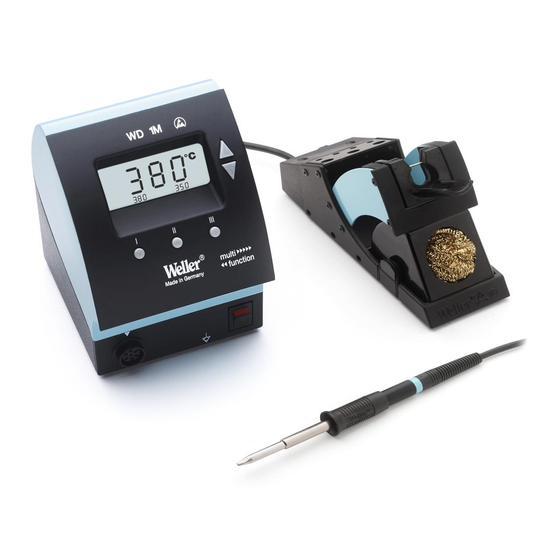
- Page 2 WD 1 (M) / WD 1000 (M) WD 1 (M) WD 1000 (M) Equipment overview Display UP button DOWN button Temperature button III Temperature button II Temperature button I Mains switch Equipotential-bonding socket Connecting socket for soldering tool 10 USB interface, B-Mini...
-
Page 3: Table Of Contents
6 Operating the device ..............8 7 Special functions ................ 9 8 Resetting to factory settings ............17 9 WD 1 (M) / WD 1000 (M) care and maintenance ...... 17 10 Fault messages and fault elimination ........17 11 Accessories ................18 12 Disposal .................. -
Page 4: For Your Safety
Always pass on the WD 1 (M) / WD 1000 (M) soldering station to third parties together with these operating instructions. Specified use... -
Page 5: Device Description
WD 1 (M) / WD 1000 (M) 5-18 4 Device description The Weller WD 1 (M) / WD 1000 (M) is a versatile soldering station for performing professional repair work on state-of-the-art electronic assemblies in the industrial engineering sector as well as repair workshops and laboratories. - Page 6 − can carry out a software update ("Firmware Updater“) on your control unit and − can remote-control the control unit and graphically display, store and print temperature curves ("Monitor Software“). Note Control units WD 1 and WD 1000 can be retrofitted with a USB interface.
-
Page 7: Starting Up The Device
− Continuous illumination indicates that the system is warming up. − Flashing light indicates that the preselected temperature has been reached. Note Please refer to the accessories section on page 18 for a list of tools that can be connected to the WD 1 (M) / WD 1000 (M). -
Page 8: Operating The Device
8-18 WD 1 (M) / WD 1000 (M) 6 Operating the device Setting the temperature Setting the temperature individually 1. Switch on the device at the mains power switch (7). The display indicates the actual temperature value. 2. Press the UP or DOWN button. -
Page 9: Special Functions
− Switch off the system if you do not intend to use the soldering iron for longer periods or activate the Weller temperature reduction function − Coat the tip before placing the soldering iron in the holder. - Page 10 10-18 WD 1 (M) / WD 1000 (M) Selecting Menu 1 special functions Special functions Navigation STANDBY SETBACK AUTO OFF OFFSET WINDOW EXIT °C / °F 1. Press and hold down the UP and DOWN buttons simultaneously. "– 1 –“ appears in the display after 2 s.
- Page 11 WD 1 (M) / WD 1000 (M) 11-18 Setting temperature deactivation (SETBACK) When the soldering tool is not in use, the temperature is reduced to the standby temperature after the set setback time has elapsed. The setback state is indicated by a flashing actual value and "STANDBY“...
- Page 12 12-18 WD 1 (M) / WD 1000 (M) Temperature performance with different settings of the SETBACK and AUTO OFF functions Settings Temperature performance without switching holder SETBACK time OFF time [1-99 mins] [1-999 mins] Soldering tool remains at the set soldering temperature.
- Page 13 WD 1 (M) / WD 1000 (M) 13-18 Setting the temperature offset The real soldering-tip temperature can be adapted by entering a temperature offset around ± 40 °C (± 72 °F). 1. Select the menu item OFFSET in Menu 1.
- Page 14 Setting the station identification (ID code) When the optional USB port is used, several WD 1 (M) / WD 1000 (M) soldering stations can be activated and remote-controlled to their full operational extent. To this end, each station requires a station identification (ID code) so that it can clearly identified.
- Page 15 WD 1 (M) / WD 1000 (M) 15-18 Executing the calibration function (Factory Calibration Check) With the FCC function you can check the temperature precision of the soldering station and compensate for possible deviations. For this purpose, the soldering-tip temperature must be measured with an external temperature meter and a temperature measuring tip assigned to the soldering tool.
- Page 16 16-18 WD 1 (M) / WD 1000 (M) Changing calibration at 450 °C / 842 °F 1. Insert the temperature sensor (0.5 mm) of the external temperature meter into the temperature measuring tip. 2. Select the menu item FCC in Menu 2.
-
Page 17: Resetting To Factory Settings
This function is described under "7.2 Selecting special functions menu 2", "Resetting calibration to factory settings" on page 14. 9 WD 1 (M) / WD 1000 (M) care and maintenance Dirt and foreign objects accumulated in the join between the heating element / sensor and the soldering tip or damage to this join may affect the accuracy of the temperature control. -
Page 18: Accessories
18-18 WD 1 (M) / WD 1000 (M) 11 Accessories T005 13 841 99 Wool balls for WDC 2 T005 15 125 99 WDC 2 Dry cleaning insert T005 15 161 99 WDH 10T Switching holder WSP 80/WP 80 T005 15 162 99... - Page 19 WD 1 / WD 1000 – Exploded Drawing...
- Page 20 WD 1 / WD 1000 – Circuit Diagram...
- Page 21 WD 1M / WD 1000M – Circuit Diagram...
- Page 22 WD 1M / WD 1000M – Exploded Drawing...
- Page 23 GERMANY GREAT BRITAIN FRANCE Weller Tools GmbH Apex Tool Group Ltd. Apex Tool Group S.A.S. Carl-Benz-Str. 2 Floor Pennine House Washington, 25 Av. Maurice Chevalier BP 46 74354 Besigheim Tyne & Wear 77832 Ozoir-la-Ferrière Cedex Phone: +49 (0) 7143 580-0 NE37 1LY Phone: +33 (0) 160.18.55.40...
Need help?
Do you have a question about the WD 1 and is the answer not in the manual?
Questions and answers