Weller WD 1 Operating Instructions Manual
Hide thumbs
Also See for WD 1:
- Operating manual (23 pages) ,
- Operating instructions manual (372 pages) ,
- Operating manual (55 pages)
Advertisement
Available languages
Available languages
Quick Links
Download this manual
See also:
Operating Manual
WD 1 (M) / WD 1000 (M)
Betriebsanleitung
Mode d'emploi
Gebruiksaanwijzing
Istruzioni per l'uso
Operating Instructions
Instruktionsbok
Manual de uso
Betjeningsvejledning
Manual do utilizador
Käyttöohjeet
√ √ ‰ ‰ Ë Ë Á Á › › Â Â ˜ ˜ Ï Ï Â Â È È Ù Ù Ô Ô ˘ ˘ Ú Ú Á Á › › · · ˜ ˜
K K u u l l l l a a n n ∂ ∂ m m k k ∂ ∂ l l a a v v u u z z u u
Návod k pouÏití
Instrukcja obs∏ugi
Üzemeltetési utasítás
Návod na pouÏívanie
Navodila za uporabo
Kasutusjuhend
Naudojimo instrukcija
Lieto‰anas instrukcija
Advertisement

Related Manuals for Weller WD 1


Summary of Contents for Weller WD 1
- Page 1 WD 1 (M) / WD 1000 (M) Betriebsanleitung √ √ ‰ ‰ Ë Ë Á Á › › Â Â ˜ ˜ Ï Ï Â Â È È Ù Ù Ô Ô ˘ ˘ Ú Ú Á Á › › · · ˜ ˜...
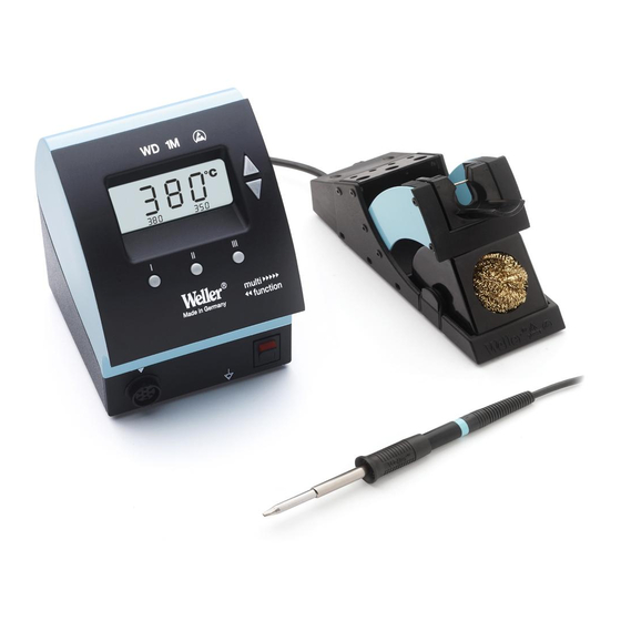
- Page 2 1. Display 1. Affichage 1. Display 2. UP Taste 2. Touche UP 2. UP-toets 3. DOWN Taste 3. Touche DOWN 3. DOWN-toets 4. Temperaturtaste III 4. Touche température III 4. Temperatuurtoets III 5. Temperaturtaste II 5. Touche température II 5. Temperatuurtoets II 6.
- Page 3 WD 1 / WD 1000 WD 1M...
- Page 4 The microprocessor-controlled soldering station Con l'interfaccia USB in dotazione, è possibile comandare a WD 1 (M) / WD 1000 (M) is part of a generation of devices distanza la stazione di brasatura mediante software PC, leg- which were developed for industrial production technology, gere e documentare i dati sulla temperatura.
- Page 5 The integrated 2 X 40W heating elements ensure that the soldering WMP: The Weller Micro Soldering Iron WMP is suitable for tip temperature is reached very quickly and con- processing SMD electronics due to its manageable trolled precisely.
-
Page 6: Special Functions
English 3. Commissioning By actuating a temperature button, the selected specified Take care when unpacking the unit and accessories. value appears for approx. 2 s in the display. During this dis- Place the soldering tool in the safety rest. play, the temperature symbol flashes. After this, the display Insert the soldering iron plug in the connection socket (9) of switches back automatically to the actual value display. - Page 7 English 4 sec. EXIT 2 sec. STANDBY III (EXIT) SETBACK 4.1 Special functions menu 1 If the UP and DOWN buttons are pressed simultaneously, after approx. 2 s the menu selection for the special functions OFFSTET is activated and - I - appears in the display, release buttons. WINDOW Menu 1 °C / °F...
- Page 8 English status is ended by pressing the UP or DOWN button. In the case of soldering work with very low heat require- ment, the reliability of the Setback function may be impaired. Change the setback time with the UP or DOWN button. Switch to previous menu item with I.
- Page 9 English the temperature buttons I, II, III is possible. “OFF” appears in the display. EXIT The “ ” symbol in the display flashes. The UP or DOWN button can be used to enter a 3-digit interlock code. Confirm the code by pressing the III button for 5 sec.: the station is locked and the “...
-
Page 10: Usb Interface
The WD 1M control unit is equipped with a Mini USB interface temperature matches that shown on the display, press the II as standard. This can retrofitted on the WD 1 control unit. key (CAL) to confirm by the temperature deviation is reset to (See Page 167). -
Page 11: Potential Balance
Soldering tips 161-165 Before long work breaks, switch the soldering system Exploded drawing WD 1, see page 168 off, or use the Weller function for temperature decrease Circuit diagram WD 1, see page 169 when not in use. Exploded drawing WD 1M, see page 170 Circuit diagram WD 1M, see page 171 Coat the tip before placing the soldering iron in the rest. - Page 12 Loddeværktøjerne selv genkendes auto- matisk af WD 1 (M) / WD 1000 (M), og tilordnes de respekti- ve styringsparametre. Efterkalibreringer kan derved i stor 1. Bemærk! udstrækning undgås.
- Page 13 Las resistencias integradas (2 x 40 W) permiten a la punta alcanzar la temperatura con WMP: Weller Micro Loddekolbe WMP er som følge af sit extremada rapidez y precisión. Gracias a un sen- fleksible koncept velegnet til bearbejdning af pro sor incorporado en el mango, la pinza de desoldar fessionel SMD-elektronik.
- Page 14 Dansk Derefter vises kort den indstillede temperatur (nominel værdi). Derefter skifter elektronikken automatisk over på den faktiske værdi. “ ”-symbolet kommer frem og de 3 faste temperaturer fra temperaturtasterne I, II, III vises. “ ”-sym- bolet tjener som optisk styringskontrol. Vedvarende lys bety- der, at systemet er ved at varme op.
- Page 15 Dansk 4.1. Specialfunktioner menu 1 (100 - 300°C / 200 - 600°F). Ved at trykke samtidigt på UP- og DOWN-tasterne, fremkal- des menuen for specialfunktionen efter ca. 2 sek., og dis- Indstil Standby-temperaturen med UP- eller DOWN-tasten. playet viser - I - ; tasterne slippes. Gå...
- Page 16 Dansk 4.1.6 Veksel mellem °F/°C 4.1.4 Setback-tid Veksel af temperaturversion fra °C til °F eller omvendt. Når loddeværktøjet ikke er i brug, sænkes temperaturen Veksel mellem °C og °F med UP / DOWN-tasterne. automatisk efter udløb af den indstillede Setback-tid til Gå...
- Page 17 Dansk 100°C/212°C 450°C/842°F Confirmation Confirmation EXIT EXIT 5 sec. Vælg kaliberingspunkt med UP- eller DOWN-tasten. Taste III 4.2. Specialfunktioner menu 2 anvendes til at forlade menuen med (EXIT). Ved at trykke samtidigt på UP- og DOWN-tasterne, aktiveres UP-taste kalibreringspunkt 450°C / 842°F menuliste 2 for kalibreringsfunktionen og stationsidentifika- DOWN-taste kalibreringspunkt 100°C / 212°F tionen efter ca.
- Page 18 Styreenheden WD 1M har som standard et mini-USB-inter- Stationen regulerer ved 450°C / 842°F. Så snart temperatu- face. Dette kan også eftermonteres på styreenheden WD 1 ren har nået en statisk tilstand (reguleringskontrollen blin- (se side 167). Anvendelse af USB-interfacet sker gennem ker), sammenlignes loddespidsens temperatur (eksternt standardsoftware fra WELLER (CD medfølger).
- Page 19 (CD) USB-kabel USB-kabel Anbring loddemidlet på loddestedet, ikke på loddespidsen. Loddespids side161-165 Eksplo-tegning WD 1 side 169 Udskift loddespidsen med det dertilhørende værktøj. Eldiagram WD 1 side 170 Eksplo-tegning WD 2M side 171 Undgå at udøve mekanisk kraft på loddespidsen.
- Page 20 Soldering Tips LT- Spitzen Soldering Bestell-Nr. Modell Beschreibung Breite A Dicke B Länge C Order-No Model Description Width A Length B Length C 005 44 437 99 LT H Meisselform 0,8 mm 0,4 mm 11,5 mm Chisel 005 44 430 99 LT HHPB Meisselform* 0,8 mm 0,4 mm 11,5 mm Chisel*...
- Page 21 Soldering Tips Bestell-Nr. Modell Beschreibung Breite A Dicke B Länge C Order-No Model Description Width A Length B Length C 005 44 427 00 LT AX Meisselform gebogen 30° 1,6 mm 0,8 mm 12,5 mm Chisel bent 30° 005 44 480 00 LT AXLF Meisselform gebogen** 1,6 mm 0,8 mm 12,5 mm Chisel bent**...
- Page 22 Soldering Tips Bestell-Nr. Modell Beschreibung Breite A Dicke B Länge C Order-No Model Description Width A Length B Length C 005 44 423 99 LT 1L Konisch lang ø 0,2 mm 19,0 mm Concial long 005 44 406 99 LT S Konisch lang ø...
- Page 23 Soldering Tips Spitzenpaar für WMRT Tip set for WMRT RTW 1 Punktspitze 0,2 mm x 45° RTW 1 Point tip 0,2 mm x 45° RTW 2 Meisselspitze 0,7 mm x 45° RTW 2 Chisel tip 0,7 mm x 45° RTW 3 Lötspitze 3,0 mm x 45° RTW 3 Soldering tip 3,0 mm x 45°...
- Page 24 Soldering Tips RT- Spitzen RT- Soldering Tips Bestell-Nr. Modell Beschreibung Order-No Model Description 005 44 601 99 RT1 Nadelspitze Needle Tip 00544 602 99 PunktspitzeR0,4 Point Tip R0,4 00544 603 99 Meißelspitze 1,3 x 0,4 mm Chisel Tip 1,3 x 0,4 mm 00544 604 99 Meißelspitze 1,5 x 0,4 mm Chisel Tip 1,5 x 0,4 mm...
- Page 25 Setback function...
- Page 26 USB interface...
- Page 27 Exploded Drawing WD 1...
- Page 28 Circuit Diagram WD 1...
- Page 29 Exploded Drawing WD 1M...
- Page 30 Circuit Diagram WD 1M...
Need help?
Do you have a question about the WD 1 and is the answer not in the manual?
Questions and answers