Table of Contents
Advertisement
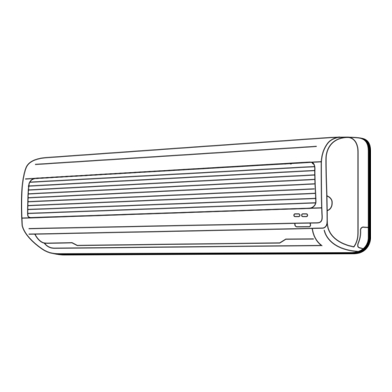
SERVICE MANUAL
TECHNICAL INFORMATION
FOR SERVICE PERSONNEL ONLY
RAS-25CNH11
RAC-25CNH11
TYPE
MODEL
POWER SOURCE
TOTAL INPUT
TOTAL AMPERES (RATED / MAX.)
Cooling CAPACITY
Heating CAPACITY
DIMENSIONS
NET WEIGHT
SPECIFICATIONS AND PARTS ARE SUBJECT TO CHANGE FOR IMPROVEMENT
ROOM AIR CONDITIONER
JANUARY 2003
(W)
(A)
(kW)
(B.T.U./h)
(kW)
(B.T.U./h)
W
(mm)
H
D
(kg)
Indoor Unit + OUTDOOR UNIT
PM
RAS-25CNH11
RAC-25CNH11
REFER TO THE FOUNDATION MANUAL
SPECIFICATIONS --------------------------------------------------------------4
Safety Precaution ------------------------------------------------------6
HOW TO USE -------------------------------------------------------------------8
Construction And Dimensional Diagram ---------------- 29
Main Parts Component --------------------------------------------- 30
Wiring Diagram ----------------------------------------------------------- 33
Circuit Diagram ---------------------------------------------------------- 35
Block Diagram ------------------------------------------------------------ 39
Basic Mode ------------------------------------------------------------------ 41
Auto Swing Function------------------------------------------------- 54
Description Of Main Circuit Operation ------------------ 55
Refrigerating Cycle Diagram ---------------------------------- 86
SERVICE CALL Q & A ----------------------------------------------------- 87
Trouble Shooting ------------------------------------------------------ 91
Parts List And Diagram------------------------------------------- 113
WALL TYPE
INDOOR UNIT
RAS-25CNH11
1ø 220V 50Hz
910 (190 ` 1,150) [COOL] / 1,250 (160 ` 1,350) [HEAT]
4.20 ` 3.85 [COOL] / 5.75 ` 5.25 [HEAT]
2.50 (0.90 ` 2.80)
8,870 (3,070 ` 9,550)
3.60 (0.90 ` 4.00)
12,280 (3,070 ` 13,650)
744
248
168
5.5
H.A.P.M.
NO. 0164E
CONTENTS
RAC-25CNH11
700
570
210
29
Advertisement
Table of Contents
Troubleshooting

Subscribe to Our Youtube Channel
Related Manuals for Hitachi RAS-25CNH1


Summary of Contents for Hitachi RAS-25CNH1
-
Page 1: Service Manual
NO. 0164E RAS-25CNH11 SERVICE MANUAL RAC-25CNH11 TECHNICAL INFORMATION REFER TO THE FOUNDATION MANUAL FOR SERVICE PERSONNEL ONLY CONTENTS SPECIFICATIONS --------------------------------------------------------------4 SAFETY PRECAUTION ------------------------------------------------------6 HOW TO USE -------------------------------------------------------------------8 CONSTRUCTION AND DIMENSIONAL DIAGRAM ---------------- 29 MAIN PARTS COMPONENT --------------------------------------------- 30 RAS-25CNH11 WIRING DIAGRAM ----------------------------------------------------------- 33 CIRCUIT DIAGRAM ---------------------------------------------------------- 35 BLOCK DIAGRAM ------------------------------------------------------------ 39 BASIC MODE ------------------------------------------------------------------ 41... - Page 2 SAFETY DURING REPAIR WORK 1. In order to disassemble and repair the unit in question, be sure to disconnect the power cord plug from the power outlet before starting the work. 2. If it is necessary to replace any parts, they should be replaced with respective genuine parts for the unit, and the replacement must be effected in correct manner according to the instructions in the Service Manual of the unit.
- Page 3 WORKING STANDARDS FOR PREVENTING BREAKAGE OF SEMICONDUCTORS 1. Scope The standards provide for items to be generally observed in carrying and handling semiconductors in relative manufacturers during maintenance and handling thereof. (They apply the same to handling of abnormal goods such as rejected goods being returned).
- Page 4 (6) Use a three wire type soldering iron including a grounding wire. Metal plate (of aluminium, stainless steel, etc.) Working table Resistor of 1 M (1/2W) Staple Earth wire Bare copper wire (for body earth) Fig. 3. Grounding of the working table Soldering iron Grounding wire...
- Page 5 CAUTION In quiet operation or stopping the running, slight flowing noise of refrigerant in the refrigerating cycle is heard occasionally, but this noise is not abnormal for the operation. When it thunders near by, it is recommend to stop the operation and to disconnect the power cord plug from the power outlet for safety.
- Page 6 SPECIFICATIONS MODEL RAS-25CNH11 RAC-25CNH11 FAN MOTOR 20 W FAN MOTOR CAPACITOR FAN MOTOR PROTECTOR COMPRESSOR GR20DR2F ---------- COMPRESSOR MOTOR CAPACITOR OVERLOAD PROTECTOR OVERHEAT PROTECTOR FUSE POWER RELAY, STICK RELAY POWER SWITCH TEMPORARY SWITCH SERVICE SWITCH TRANSFORMER 416NR VARISTOR NOISE SUPPRESSOR REMOTE CONTROL SWITCH (LIQUID CRYSTAL) THERMOSTAT YES (IC)
- Page 7 The Length of Indoor Unit Connecting Cord about 0.9m about 1.6m Figure showing the Installation of Indoor and Outdoor Unit. Cut away shaded portion, and finish the edge of the opening so that there is no burr. Be sure to Direction of Piping above 50mm completely...
-
Page 8: Safety Precaution
SAFETY PRECAUTION Please read the “Safety Precaution” carefully before operating the unit to ensure correct usage of the unit. Pay special attention to signs of “ Warning” and “ Caution”. The “Warning” section contains matters which, if not observed strictly, may cause death or serious injury. The “Caution” section contains matters which may result in serious consequences if not observed properly. - Page 9 PRECAUTIONS DURING OPERATION The product shall be operated under the manufacturer specification and not for any other intended use. Do not attempt to operate the unit with wet hands, this could cause fatal accident. When operating the unit with burning equipments, regularly ventilate the room to avoid oxygen insufficiency.
-
Page 10: Names And Functions Of Each Part
NAMES AND FUNCTIONS OF EACH PART INDOOR UNIT Air filter To prevent dust from coming into the indoor unit. (Refer page 25) Indoor unit indicators Light indicator showing the operating condition. (Refer page 9) Front panel (Air Inlet) Horizontal deflector Vertical deflector (Air Outlet) (Refer page 20) - Page 11 OPERATION INDICATOR TEMPORARY SWITCH Use this switch to start and stop when the remote controller does not work. By setting the temporary switch, the operation is done in previously set operation mode. When the operation is done using the temporary switch after the power source is turned off and turn on again, the operation is done in automatic mode.
-
Page 12: Names And Functions Of Remote Control Unit
NAMES AND FUNCTIONS OF REMOTE CONTROL UNIT REMOTE CONTROLLER This controls the operation of the indoor unit. The range of control is about 7 meters. If indoor lighting is controlled electronically, the range of control may be shorter. This unit can be fixed on a wall using the fixture provided. Before fixing it, make sure the indoor unit can be controlled from the remote controller. -
Page 13: Automatic Operation
AUTOMATIC OPERATION The device will automatically determine the mode of operation, HEAT, COOL or DEHUMIDIFY depending on the initial room temperature. The selected mode of operation will not change when the room temperature varies. Press the FUNCTION selector so that the display indicates the (AUTO) mode of operation. -
Page 14: Heating Operation
HEATING OPERATION Use the device for heating when the outdoor temperature is under 21°C. When it is too warm (over 21°C), the heating function may not work in order to protect the device. Press the FUNCTION selector so that the display indicates (HEAT). -
Page 15: Dehumidifying Operation
DEHUMIDIFYING OPERATION Use the device for dehumidifying when the room temperature is over 16°C. When it is under 15°C, the dehumidifying function will not work. START Press the (START/STOP) button. Dehumidifying operation ˚ starts with a beep. Press the button again to stop operation. STOP Press the FUNCTION selector so that the display indicates (DEHUMIDIFY). -
Page 16: Cooling Operation
COOLING OPERATION Use the device for cooling when the outdoor temperature is 22-42°C. If in doors humidity is very high (80%), some dew may form on the air outlet grille of the indoor unit. Press the FUNCTION selector so that the display indicates (COOL). -
Page 17: Fan Operation
FAN OPERATION You can use the device simply as an air circulator. Use this function to dry the interior of the indoor unit at the end of summer. Press the FUNCTION selector so that the display indicates (FAN). Press the (FAN SPEED) button.* START Press the... -
Page 18: How To Set The Timer
HOW TO SET THE TIMER Time, Day, Month Set the current month and TIME, DAY, day with the TIMER control After you change the MONTH button. batteries; (current time, day, month) OFF TIMER RESET ON TIMER OFF-Timer Press the (OFF-TIMER) button. - Page 19 Set the current time with the Press the (TIME) button again. Press the TIMER control button. The time indication starts lighting (TIME) button. instead of flashing. The time indication will disappear automatically in 10 second. To check the current time setting, press the (TIME) button twice.
-
Page 20: How To Set The Sleep Timer
HOW TO SET THE SLEEP TIMER Set the current time at first if it is not set before (see the pages for setting the current time). Press the (SLEEP) button, and the display changes as shown below. Mode Indication 1 hour 2 hours 3 hours 7 hours... - Page 21 Explanation of the sleep timer The device will control the FAN SPEED and room temperature automatically so as to be quiet and good for people’s health. You can set the sleep timer to turn off after 1, 2, 3 or 7 hours. The FAN SPEED and room temperature will be controlled as shown below.
-
Page 22: Adjusting The Air Deflector
ADJUSTING THE AIR DEFLECTOR Adjustment of the conditioned air in the upward and downward directions. The horizontal air deflector is automatically set to the proper angle suitable for each operation. The deflector can be swung RESET up and down continuously and also set to the desired angle using the “... -
Page 23: How To Exchange The Batteries In The Remote Controller
HOW TO EXCHANGE THE BATTERIES IN THE REMOTE CONTROLLER Remove the cover as shown in the figure and take out the Push and pull to the old batteries. direction of arrow Install the new batteries. The direction of the batteries should match the marks in the case. - Page 24 THE IDEAL WAYS OF OPERATION Suitable Room Temperature Install curtain or blinds Warning It is possible to Freezing temperature reduce heat is bad for health and a entering the waste of electric power. room through windows. Ventilation Effective Usage Of Timer At night, please use the “OFF or ON timer Caution operation mode”, together with your wake up...
- Page 25 FOR USER’S INFORMATION The Air Conditioner And The Heat Source In The Room Caution If the amount of heat in the room is above the cooling capability of the air conditioner (for example: more people entering the room, using heating equipments and etc.), the preset room temperature cannot be achieved.
-
Page 26: Attaching The Air Cleansing And Deodorizing Filters
ATTACHING THE AIR CLEANSING AND DEODORIZING FILTERS Before installation, be sure to stop the operation by using the remote controller. Open the front panel. Pull up the front panel holding it at both sides by both hands. Front panel Remove the filter. Push the filter upward to release the claws Front cover and pull out the filter. - Page 27 MAINTENANCE CAUTION Before the cleaning, stop operation and disconnect the power supply. AIR FILTER Clean the air filter, as it removes dust inside the room. In case the air filter is full of dust, the air flow will decrease and the cooling capacity will be reduced. Further, noise may occur. Be sure to clean the filter following the procedure below.
- Page 28 Washable Front Panel Remove the front panel and wash with clean water. Wash it with a soft sponge. After using neutral detergent, wash thoroughly with clean water. When front panel is not removed, wipe it with a soft dry cloth. Wipe the remote controller thoroughly with a soft dry cloth.
- Page 29 CAUTION Cleaning and maintenance must be carried out only by qualified service personal. Before cleaning, stop operation and switch off the power supply. MAINTENANCE AT BEGINNING OF LONG OFF PERIOD Run the unit by setting the operation mode to (COOL), the temperature to 32°C and the fan speed to HI for about half a day on a fine day, and dry the whole of the unit.
- Page 30 AFTER SALE SERVICE AND WARRANTY WHEN ASKING FOR SERVICE, CHECK THE FOLLOWING POINTS. CONDITION CHECK THE FOLLOWING POINTS Is the fuse all right? Is the voltage extremely high or low? When it does not operate Is the circuit breaker “ON”? Was the air filter cleaned? Does sunlight fall directly on the outdoor unit? When it does not cool well...
-
Page 31: Construction And Dimensional Diagram
CONSTRUCTION AND DIMENSIONAL DIAGRAM MODEL RAS-25CNH11 Top air suction grill Wireless remote controller Air suction grill Front cover Mounting plate Cabinet Discharge grill Horizontal air deflector Vertical air deflector (147) VIEWED FROM BACK Drain cap connection part (PIPE LEAD-OUT) When piping is drawn horizontally, exchange About 350 About 280... - Page 32 MAIN PARTS COMPONENT THERMOSTAT Thermostat Specifications MODEL RAS-25CNH11 THERMOSTAT MODEL 17.6 (63.7) INDICATION 16.6 (61.8) TEMPERATURE 25.6 (78.1) INDICATION °C (°F) 24.6 (76.3) 33.6 (92.5) INDICATION 32.6 (90.7) FAN MOTOR Fan Motor Specifications MODEL RAS-25CNH11 RAC-25CNH11 RATED VOLTAGE DC0 – 35V DC230V OUTPUT WHITE...
- Page 33 COMPRESSOR MOTOR Compressor Motor Specifications MODEL RAC-25CNH11 COMPRESSOR MODEL GR20DR2F PHASE SINGLE RATED VOLTAGE AC 220 – 240 V RATED FREQUENCY 50 Hz POWER SOURCE FOR COMPRESSOR Vcc max = 360V POLE NUMBER WHITE CONNECTION YELLOW 20°C 2M = 3.21 (68°F) RESISTANCE VALUE 75°C...
- Page 34 WIRING DIAGRAM MODEL RAS-25CNH11 / RAC-25CNH11 Indoor unit CAUTION AC 220V The marked parts are very 5 0 H Z important ones for safety. C O N N E C T I N G T E R M I N A L B OA R D C A B L E BROWN BROWN...
- Page 35 CIRCUIT DIAGRAM MODEL RAS-25CNH11 – 35 –...
- Page 36 CIRCUIT DIAGRAM MODEL RAC-25CNH11 – 37 –...
- Page 37 BLOCK DIAGRAM MODEL RAS-25CNH11/RAC-25CNH11 INDOOR UNIT OUTDOOR UNIT Outdoor DC fan motor Power switch Magnetic relay Power module Power circuit Inrush current DC compressor Protection circuit motor DC current signal Rotor magnetic pole position detection circuit Trip signal Upper arm synthesiz circuit drive circuit Peak current cut off...
- Page 38 BASIC MODE MODEL RAS-25CNH11 Table 1 Operation mode Cooling Dehumidifying Heating Auto Model RAS-25CNH11 Data Basic Start Stop Start Stop operation of Start / stop switch Source Label Required value of file name name unit side Operation lamp Start/Stop WMAX 5400 min switch WSTD...
- Page 39 Operation mode Cooling Dehumidifying Heating Auto Changes to "Med" or "Lo" from "Hi" Operation mode is changed to one The following operation mode is according to the room of "Super lo", "Lo", "Med", "Hi", set depending on the room "Super Hi" and "Stop" according to temperature.
- Page 40 BASIC COOLING OPERATION Table 1 TCMAX Table 2 Dewing condition judgement value Max. speed (CMAX) — Room temp. — Preset CLMXTP Item Temperature Min. speed (CMIN) temp. (including shift) Dewing 650min 1.66˚C 30˚C Room temp. condition (ON) 750min 2.00˚C Dewing 32˚C condition (OFF) 800min...
- Page 41 Cooling defrost Dehumidifying Indoor unit heat exchager temperature Room temperature 30 sec. judgement Room temperature TEIOF TEION Cooling preset Thermostat temperature judgement Thermostat OFF Room temperature Refer to the basic operation. Indoor fan judgement 15 sec. Outdoor fan 30 sec. Start/Stop Switch Operation lamp minimum 3 min.
- Page 42 COOL RHYTHM Room temp. Minimum Minimum Minimum Minimum 5 min. 5 min. Minimum 5 min. 5 min. 5 min. 5 min. 5 min. 5 min. Minimum 5 min. 5 min. 5 min. Final Preset temperature Cooling Preset temperature (normal) Cooling Preset temperature (rhythm) Thermostat OFF Thermostat judgement...
- Page 43 Basic heating operation Table 1 Speed specification during fixed rotation period S t d td (Hot dash time) Wtd Less than 10 minutes 2150min 1700min 10 minutes to less 3150min 2500min than 20 minutes 20 minutes or more 4150min 3300min Preset temperature for heating (+)SHIFTW...
- Page 44 Reversing valve defrost More than 15’ AUTO FRESH DEFROST More than DFTIM 30’ 30’ Fan speed Stop "Hi" setting Start/Stop switch Defrost signal Preheating OFF Preheating judgement Indoor fan 10’ Super Lo 15’ Outdoor fan Operation lamp Reversing valve (Power ON mode in heating) 30’...
- Page 45 AUTO SWING FUNCTION PRESENT CONDITION INPUT SIGNAL OPERATING SPECIFICATION REFERENCE OPERATION OPERATION MODE AIR DEFLECTOR ONE SWING (CLOSING AIR DEFLECTOR) INITIALIZE AT NEXT 1 DOWNWARD STOP OPERATION. STOP EACH MODE 2 UPWARD KEY INPUT DURING ONE SWING STOP AT THE MOMENT. START SWINGING AUTO COOL 1 DOWNWARD...
-
Page 46: Description Of Main Circuit Operation
DESCRIPTION OF MAIN CIRCUIT OPERATION Model RAS-25CNH11 1. Reset Circuit 35V 5V 5V 12V Q202 NORMAL RESET ZD201 – MICRO COMPUTER Fig. 1-1 Voltage 35V DC line 5V DC line Base of Q201 Power is ON Power is OFF Collector of Q202 Fig. - Page 47 2. Receive Circuit R709 R710 C701 ZD701 – LIGHT Wireless input RECEIVING R705 UNIT C702 Micro computer Fig. 2-1 The Light receiving unit receives an infrared signal from the wireless remote control. The receiver amplifies and shapes the signal and outputs it. 3.
- Page 48 4. Auto Sweep Motor Circuit Auto sweep motor for horizontal air deflectors Micro computer Rotor IC501 Fig. 4-1 Auto Sweep Motor Circuit (Horizontal air deflectors) Fig. 4-1 shows the Auto sweep motor drive circuit; the signals shown in Fig. 4-2 are output from pins –...
- Page 49 5. Room Temperature Thermistor Circuit Fig. 5-1 shows the room temperature The voltage at A depends on the room thermistor circuit. temperature as shown in Fig. 5-2. Room Micro temperature computer thermistor R309 Room temp. input R310 C302 Fig. 5-1 Room temperature (˚C) Fig.
- Page 50 7. Temporary Switch R709 R710 TEMPORARY SWITCH C701 ZD701 SW701 37 X1 MICRO COMPUTER Fig. 7-1 Fig. 7-1 The temporary switch is used to operate the air conditoner temporarily when the wireless remote control is lost or faulty. The air conditioner operates in the previous mode at the previously set temperature. However, when the power switch is set to OFF, it starts automatic operation.
- Page 51 PWM output Voltage at I Voltage at J Output voltage Fig. 8-2 Fan Motor Set Wind Velocity and DC Voltage (between blue and red) Characteristics Mode Connector blue-red voltage (V) Rotation Speed (min Fan Speed 16.6 19.1 1,040 OVERLOAD 19.1 1,040 27.7 1,350...
- Page 52 9. 12V Power Circuit R101 R104 REG1 L102 D102 R102 C102 – C105 R103 Fig. 9 — 1 DC 35V supplied from the outdoor unit is controlled by switching of regulator 1, and is smoothed by D102, L102 and C102 to produce 12V. Output voltage is divided by R102 and R103, and input to output dividing pin to control switching, so that output voltage is 12V.
- Page 53 Model RAC-25CNH11 1. Power Circuit Diode stack Reactor Terminal board Stick relay 15A fuse NF coil £ £ ‡ ‡ ‡ ‡ Black C807 Varistor 1 C812 R802 Inrush current Surge C805 absorber protection relay Green C806 0 0 0 R807 R801 ‡...
- Page 54 (3) Smoothing capacitor This smoothes (averages) the voltage rectified by the diode stacks. £ £ ‡ (DC valtage) ‡ £ £ Fig. 1-2 Both ends of R802 DC voltmeter or teste (same as oscilloscop) Fig. 1-4 < Reference > DC voltage can be measured by connecting both ends of R802 the control P.W.B.
- Page 55 2. Indoor/Outdoor Interface Circuit The interface circuit superimposes an interface signal on the 36V DC line supplied from the outdoor unit to perfom communications between indoor and outdoor units. This circuit consists of a transmiting circuit which superimposes an interface signal transmit from the micro computer on the 35V DC line and a transmiting circuit which detects the interface signal on the 35V DC line and outputs it to the micro computer.
- Page 56 Fig. 2-1 shows the interface circuit used for the indoor and outdoor micro computers to communicate with each other. COM801 R805 R810 IF receive R803 C801 R802 R807 input R808 R811 R804 (SDI) C804 C802 D801 R809 C803 R806 Micro R817 computer R813...
- Page 57 Outdoor HIC Indoor micro computer 35V DC line 33ms. 100 ms. Leader 1frame Fig. 2-2 Voltages Waveforms of indoor / Outdoor Micro computers (Outdoor to Indoor Communications) Outdoor HIC Indoor micro computer 35V DC line 33ms 4.95ms. 1frame Transmit / receive switching time Fig.
- Page 58 3. Power Module Circuit £ £ – 67 –...
- Page 59 DC 230V is input to power module and power module switches power supply current according to rotation position of magnet rotor. The switching order is as shown in Fig. 3-2. At point E: U + is ON, V – is ON (circuit in Fig. 3-1) At point F: U + is chopped (OFF), V –...
- Page 60 Power module ‡ ‡ £ £ £ DC compressor U coil motor µ 1000 F £ £ £ V coil R806 ‡ ‡ W coil DC current (Id) MP6501 detection resistor Fig. 3-4 Power module circuit (U + is ON, V – is ON) Since current flows at point B only when U+ transistor is ON, the current waveform at point B becomes intermittent waveform as shown in Fig.
- Page 61 4. Power Circuit for P.W.B. Fig. 4-1 shows the power circuit for P.W.B. and waveform at each point. (12 - C) (12 - C) (12 - C) (12 - D) 3A fuse (12 - D) (12 - E) (12 - E) C810 (12 - H) RC61...
- Page 62 (2) During ON period Collector current of Q1 is increased directly. In this period, base current is fixed by saturation characteristic of transformer. (3) Shifting from ON to OFF In this circuit, feed back (negative) is applied from 12V output. When voltage between both ends of C65 reaches the specified value, M51 is turned ON and current flows between pin 1 and 2 of P151, secondary side is turned ON, current flows to base of Q2 via R9 and D4, Q2 is turned ON, and Q1 base current is bypassed to turn Q1 OFF.
- Page 63 <Reference> • When power circuit for P.W.B. is estimated as abnormal: (1) Check that power voltages of 5V, 12V on the control P.W.B., and also power voltage of upper arm U, V and W and lower arm are specified values. PQ601 603 ±...
- Page 64 5. Reversing valve control circuit I/F 35V Reversing valve R 233 £ D 701 PQ 701 Q 701 8E21 R 705 § ¤ R 706 DC voltmeter or tester I/F 0V Fig. 5 - 1 Since the reversing valve is differential pressure system, even when reversing valve is ON (collector voltage of Q701 is about 0.8V normally), compressor rotation speed instructed by indoor microcomputer exceeds 3300min - , signal at pin...
- Page 65 6. Rotor Magnetic Pole Position Detection Circuit + 12V £ £ £ £ R101 R102 R103 C104 C105 C106 C101 C102 C103 R104 R105 R106 Voltage at point about 230V Voltage at point 0.6V Voltage at point Voltage at point C - transis- B - transis- transis-...
- Page 66 7. Drive Circuit (1) Upper Arm Drive Circuit Fig. 7-1 shows the upper arm drive circuit. The circuit configuration is completely the same for phases A, B and C. Fig. 7 - 1 Fig. 7 - 2 Forward Current Waveform at Point A When pin °...
- Page 67 When pin of HIC-1 then goes "Hi" [ "Lo", a photocoupler between PQ2 pins 1 and 2 turns off and the reverse bias current flows to C501 [ power module’s Eu + terminals [ Bu + terminals [ R504 [ PQ501 Switching incomplete to cut off the upper arm transistors.
- Page 68 (2) Lower Arm Drive Circuit Fig. 7-4 shows the lower arm drive circuit. The circuit configuration is completely the same for phases A, B and C. Power module R411 R414 Bu - A - phase R412 R415 Bv - B - phase R413 R416 R417...
- Page 69 8. HIC and Peripheral Circuits Fig. 8-1 shows the micro computer and its peripheral circuits, Table 8-1, the basic operations of each circuit block, and Fig. 8-2, the system configuration. HIC - 1 Power module positive terminal R229 AVcc R230 C204 R231 Micro computer...
- Page 70 Reset voltage Chopper signal DC current Reset circuit Reset Signal Trip signal Peak current cut synthesis circuit off circuit Chopper signal Outdoor micro DC 260V computer 290V Ip signal (interrupt signal) Com- Overload external pressor set value circuit motor (AX-8E21) DC current level Drive Voltage amp.
- Page 71 (2) Overload control circuit (OVL control circuit) Overload control is to decrease the speed of the compressor and reduce the load when the load on the air conditioner increases to an overload state, in order to protect the compressor, electronic components and power breaker.
- Page 72 Power module HIC - 1 positive terminal R229 R230 C204 R231 Micro computer DC current (AX-8E21) R205 R201 C206 R806 Q203 R204 D202 R211 FANC R208 R206 R203 R207 Q202 Cool R222 Q201 Fig. 8-8 Voltage at HIC Voltage at HIC Rotation speed of compressor Commanded rotation speed Actual rotation speed...
- Page 73 R229, R230, R231 detect the DC voltage at the power circuit. The micro computer receives a DC voltage (210-300V) via HIC and applies correction to the overload set value so the DC current is low (high) when the DC voltage is high (low). (Since the load level is indicated by the DC voltage multiplied by DC current, R229, R230, R231 are provided to perform the same overload judgement even when the voltage varies.) Amplification : low...
- Page 74 9. Trip Signal Synthesis Circuit Fig. 9-1 shows the trip signal synthesis circuit. This circuit is provided to stop the drive signal, etc. according to whether or not the Ip cut signal or reset signal is present. HIC - 1 Z0301 R232 Micro...
- Page 75 10. Temperature Detection Circuit Over heat Over heat thermistor thermistor Normal: 2.7V or less Normal: 2.7V or less Over heat: 2.7V or more Over heat: 2.7V or more Reset: Reset: 2.3V or less 2.3V or less Over heat Over heat R301 R301 Defrost...
- Page 76 11. Reset Circuit HIC-1 ZD301 R232 Micro computer AX-8E21 Normal: Hi RESET Reset: Fig. 11-1 Reset circuit performs initial setting of the microcomputer program before power is turned on. Microcomputer resets program with reset voltage set to Lo, and program can be operated with Hi. Fig.
-
Page 77: Refrigerating Cycle Diagram
REFRIGERATING CYCLE DIAGRAM COOLING OUTDOOR UNIT SERVICE VALVE INDOOR UNIT (3/8) SINGLE-ENDED UNION (3/8) SUCTION TANK REVERSING VALVE HEATING CAPILLARY SINGLE-ENDED UNION (1/4) CHEK COOLING / FILLING VALVE HEATING PIPE CAPILLARY HEATING OUTDOOR UNIT INDOOR UNIT SERVICE VALVE (3/8) SINGLE-ENDED UNION (3/8) SUCTION TANK... - Page 78 SERVICE CALL Q & A MODEL RAS-25CNH11 /RAC-25CNH11 Cooling operation If the air conditioner operates in The compressor has stopped Check if frost has formed on the indoor unit heat exchanger. the cooling mode when it is suddenly during cooling operation.
- Page 79 Heating operation The circulation stops occasionally during the This occurs during defrosting. Walt for 5 10 minutes heating operation. until the outdoor unit is defrosted. Even when the fan speed is set to "Hi" or At the begining of the heating operation, the fan speed is "Med", the operation starts in the "Lo"...
-
Page 80: Auto Operation
Auto operation The auto fan speed mode is set automatically. In the auto operation mode, the fan speed cannot be changed using the fan speed selector switch. Automatically, Heating, Cooling or Dehumidifying is How is operation mode decided in AUTO chosen according to the room temperature. -
Page 81: Wireless Remote Controller
Even when the reserved time is the same, The Nice temperature reservation is working correctly. The turn-on time varies depending on the conditions of the the system turns on at a different time. room. In the heating operation, since the system calculates and corrects the starting time to reach the preset temperature at the reserved time under the current conditions, the operating time is defferent every day. -
Page 82: Trouble Shooting
TROUBLE SHOOTING Model RAS-25CNH11 / RAC-25CNH11 PRECAUTIONS FOR CHECKING Power source from an indoor unit 1 ∅, 220V, 50Hz Outdoor unit electric parts 1. Remember that the 0V line is biased to 155-170V in µF µF 1,000 reference to the ground level. - Page 83 DISCHARGING CAPACITORS 1. Turn off the indoor unit’s power switch or unplug the power cord, and wait for a minute or so. 2. Open the cover of the electric parts compartment. Discharge electricity µ from smoothing capacitors (1,000 F) by connecting the leads of a soldering iron of 30 75W to the terminals provided for this purpose.
- Page 84 R inproof cover (transparent) Be sure to replace the rainproof cover after checking (rainwater would enter if it is not installed). – 93 –...
- Page 85 CHECKING THE INDOOR/OUTDOOR UNIT ELECTRICAL PARTS AND REFRIGERATING CYCLE [ MODEL RAS-25CNH11 / RAC-25CNH11 ] Timer lamp Does the timer or dehumidifying lamp on See "Troubleshooting when the timer lamp the indoor unit blink? blinks". Check the outdoor electrical parts. Set to room temperature 16°C in the Dehumidifying cooling mode or to 32°C in the heating...
- Page 86 TROUBLE SHOOTING WHEN THE TIMER and DEHUMIDIFYING LAMP BLINKS MODEL RAS-25CNH11 Perform trouble shooting according to the number of times the timer lamp on the display of the indoorunit blinks Blinking made of timer lamp Reason of indication Possible caues Reversing valve defective (1) Reversing valve defective 5 sec.
- Page 87 2. Outdoor unit ( judging between “electrical parts of the condensing unit” and “refrigerating cycle”) [MODEL RAC-25CNH11] Remove the compressor Connecting connector. Compressor connecting connector If checking cannot be Set to the operation mode and done the first time, wait press the Start /Stop Switch.
- Page 88 [ MODEL RAC-25CNH11 ] ( 3 ) L I G H T I N G M O D E I N T H E O P E R AT I O N W I T H C O M P R E S S O R L E A D SELF—DIAGNOSIS LIGHTING MODE : LIT : BLINKING : OFF D I S C O N N E C T E D ( 1 ) D I S C O N N E C T T H E C O N N E C TO R S O F T H E L E A D C O N N E C T E D TO...
- Page 89 Is AC 220V voltage being generated Is AC 220V voltage being generated at Check power outlet and breaker and between terminals A and B of the terminal power outlet? repair defective parts. board? Check power cord, power switch and terminal board. Repair defective parts. Is a AC 220V voltage generated between Is a DC 35V voltage generated between terminals A and B of the terminal board...
- Page 90 The outdoor unit does not operate (remote control command can be received). Does LD701 light when the heating Check the room temperature thermis- operation is done with the tempera- tor and replace if it is defective. ture set to 32¡C using the remote 〈Normal value〉...
- Page 91 4. Only the indoor unit fan does not operate (other functions are normal). Is a voltage of DC 5V generated be- Is a voltage of DC25V-35V generated tween pins (Blue) and (Yellow) Replace the indoor unit fan motor between pins (Blue) and (Red) of CN10?
- Page 92 6. The air deflector cannot be moved(other functions are normal) Replace the micro computer. Are pulse signals output at pins of micro computer when the "auto air deflection" is set to ON in the fan operation mode? Replace REG1. Is a voltage of 15V or more generat- and G (12V line) of ed between Check IC501 and if there is no abnor-...
- Page 93 CHEKCING THE REMOTE CONTROL SWITCH Install the battery in the right polarity. Is battery polarity right? Does transmission mark light for an in- stant when the button is pressed? Replace the battery. Turn on an AM radio, bring the remote control switch within 15 cm of the radio, and press the Start / Stop switch.
- Page 94 You can check the remote control switch by other methods as explained below. Using a video monitor Connect a video camera to a TV and aim at the remote control switch. If infrared rays are emitted from the switch, you will see a flash in violet on the monitor screen. Video camera Remote control switch Using a Checker...
- Page 95 [The air conditioner does not operate at ail or cannot be operated correctly] Is 220V supplied to the A,B terminal? Is 35V being applied between C and Is chattering sound of relay heard? Because of reverse connection of C/D line, chattering occurs at I/F re- lay.
- Page 96 Is switching power circuit normal? Replace defective parts. Is 3A fuse normal? If 3A fuse has been blown, Q1, switching transformer, ZD3, etc. may be defective. Operate the outdoor unit according to the "Operation of the outdoor unit indepndently". What condition does the self- disgnosis lamp indicate? LD301: Blinking 10 times.
- Page 97 Is there DC35V output at both ends of C67? There are defective parts between brown/red jumper wire and C/D line. There are defective parts between Is DC 12V applied to both ends of the 12V output of the switching the control side (coil terminals) of power supply on the control P.W.B.
- Page 98 LD301 : Blinks 8 times. Is the power module normal? Replace the power module. Acceleration defective Perform continuity check of the Is the micro computer drive circuit leads and pattern according to the Replace defective parts. PS-HIC normal? P.W.B. diagram and circuit dia- gram.
- Page 99 LD301: Blinks 6 times. Replace parts in the thermistor Is the thermistor circuit normal? circuit. OH thermistor temperature rises LD301: Blinks 5 times. Leakage of refrigerant or Check the continuity of replaced Replace defective parts. parts. compressor defective. Overload lower limit cut Replace the control P.W.B.
- Page 100 LD301: Blinks 2 times. Is the power module normal? Replace the power module. Peak current cut Is the drive circuit normal? Replace defective parts. Replace defective parts. Is the reset circuit normal? LD301: Blinks 1 times. of the micro computer is Replace defective parts.
- Page 101 Method for diagnosis of power module MODEL MP 6501 COLECTER BASE Circuit diagram of the device (excepting the reflux diode.) EMITER Circuit diagram of the module POWER MODULE P.W.B. Terminals symbol mark of the module See next page for measuring value using tester –...
- Page 102 How to check Power module Checking power module using tester Set tester to resistance range(x100). If indicator does not swing in the following conductivity check, the power module is normal. (In case of digital tester, since built-in battery is set in reverse direction, + terminals are reversed.) CAUTION If inner circuit of power module is disconnected (open), the indicator of tester will not swing and this may assumed as...
-
Page 103: Checking The Refrigerating Cycle
(JUDGING BETWEEN GAS LEAKAGE AND CHECKING THE REFRIGERATING CYCLE COMPRESSOR DEFECTIVE) 1. Troubleshooting procedure (No operation, No heating, No cooling) Lighting mode Blinks Blinks Blinks Blinks Blinks Blinks Connect U,V,W phase leads to the Self- 2 times 3 times 4 times 5 times 6 times 8 times... - Page 104 PARTS LIST AND DIAGRAM MODEL RAS-25CNH11 – 113 –...
- Page 105 MODEL RAS-25CNH11 PART N0. Q’TY / UNIT PARTS NAME RAS-25CNH11 PMRAS-25CNH2 CABINET PMRAS-25CNH2 LOW-COVER PMRAS-25CNH2 20W MOTOR PMRAS-25CNH2 TANGENTIAL FLOW FAN PMRAS-25CNH2 P-BEA ASSEMBLY PMRAS-25CNH2 BEARING COVER PMRAS-25CNH2 FAN MOTOR SUPPORT PMRAS-25CNH2 ELECTRICAL COVER PMRAS-25CNH2 DRAIN PAN ASSEMBLY PMRAS-25CNH2 DRAIN HOSE PMRAS-25CNH2 FRONT COVER ASS’Y PMRAS-25CNH2...
- Page 106 MODEL RAC-25CNH11 – 115 –...
- Page 107 MODEL RAC-25CNH11 PART N0. Q’TY / UNIT PARTS NAME RAC-25CNH11 RA-226 O.L.R. COVER RA-226 COVER SUPPORT PMRAC-05CV FAN MOTOR SUPPORT PMRAC-25CNH2 20W MOTOR PMRAC-25CNH2 PROPELLER FAN PMRAC-25CNH11 904 CABINET PMRAC-05CV ELECTRICAL COVER ASSEMBLY PMRAC-05CV SIDE PLATE (R) PMRAC-05CV SIDE PLATE (L) PMRAC-05CV HANDLE PMRAC-05CV...
- Page 108 HITACHI RAS-25CNH11 / RAC-25CNH11 PM NO. 0164E Printed in Malaysia...
Need help?
Do you have a question about the RAS-25CNH1 and is the answer not in the manual?
Questions and answers