Table of Contents
Advertisement
Installation and Service
Instructions
for use by heating contractor
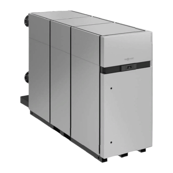
Vitocrossal 300
CA3 Series 2.5, 3.0, 3.5, 4.0, 5.0 and 6.0
Gas condensing boiler with cylinder burners
Heating input: 2500 to 6000 MBH
(733 to 1758 kW)
VITOCROSSAL 300
H
5790 733 - 07
09/2017
Product may not be exactly as shown
IMPORTANT
Read and save these instructions
for future reference.
Please file in Service Binder
Advertisement
Table of Contents

Subscribe to Our Youtube Channel
Related Manuals for Viessmann Vitocrossal 300 CA3 2.5


Summary of Contents for Viessmann Vitocrossal 300 CA3 2.5
- Page 1 Installation and Service Instructions for use by heating contractor Vitocrossal 300 CA3 Series 2.5, 3.0, 3.5, 4.0, 5.0 and 6.0 Gas condensing boiler with cylinder burners Heating input: 2500 to 6000 MBH (733 to 1758 kW) VITOCROSSAL 300 Product may not be exactly as shown IMPORTANT Read and save these instructions for future reference.
-
Page 2: Safety, Installation And Warranty Requirements
Follow the ultimate owner with all equipment, as well as safety Viessmann maintenance schedule of the boiler contained precautions/requirements, shutdown procedure, and in this manual. the need for professional service annually before the... - Page 3 Rinse washer thoroughly. page 11 in this manual. - Operations such as sawing, blowing, tear-out and Viessmann recommends installation of an additional spraying may generate airborne fiber concentration electrical disconnect switch and a fuel shut-off valve (if requiring additional protection.
-
Page 4: Table Of Contents
Table of Contents Vitocrossal 300 CA3 - 3.5, 4.0, 5.0 and 6.0 Installation/Service Page Safety Safety, Installation and Warranty Requirements .... 2 General Information Important Regulatory and Installation Requirements ..8 About these Installation Instructions ......10 Product Information ..........10 Mechanical Room .............11 For Retrofit Applications ..........11 Installation Recommended Minimum Service Clearance ....12... - Page 5 Table of Contents Vitocrossal 300 CA3 - 3.5, 4.0, 5.0 and 6.0 Installation/Service Page Venting Options - Stainless Steel/PP(s) Two Pipe System - Vertical Exhaust/ Vertical Air Intake ............68 Two Pipe System - Horizontal Exhaust/ Horizontal Air Intake ..........70 Two Pipe System - Vertical/Horizontal Installations ..71 Individual Burner Intake Ducting ......
- Page 6 Table of Contents Vitocrossal 300 CA3 Series 2.5 to 6.0 Installation/Service Page Service Further Assembly and Commissioning .......117 (continued) Checking for Flue Gas Leakage ......117 Automatic Leakage Test for Valves of the Combined Gas Valve ............. 117 Checking On-site Gas Connections for Leakage ..118 Taking Final Measurement Reading ......118 Checking the Water Conditions .......118 Checking Expansion Tank and System Pressure ..
- Page 7 Table of Contents Vitocrossal 300 CA3 Series 2.5 to 6.0 Installation/Service Page Burner Control Unit Burner Control Unit ..........187 Resetting Operating Parameters to Factory Settings ..191 Manual Mode and Service Display ......191 Burner Control Unit Flow Diagram ......192 Faults ..............194 Fault Codes ............
-
Page 8: General Information
General Information Vitocrossal 300 CA3 Series 2.5 to 6.0 Installation/Service Important Regulatory and Installation Requirements For installations on the Commonwealth of Massachusetts, the following modifications to NFPA-54 chapter 10 apply: Excerpt from 248 CMR 5-08: 2(a) For all side-wall horizontally vented gas fueled equipment installed in every dwelling, building or structure used in whole or in part for residential purposes, including those owned or operated by the Commonwealth and where the side-wall exhaust vent termination is less than (7) feet above finished grade in the area of the venting, including but not limited to decks and porches, the following requirements shall be satisfied:... -
Page 9: Important Regulatory And Installation Requirements
The gas valve of this boiler meets the the literature can be found. Contact Viessmann for requirements as set forth in the ASME CSD-1 standard. additional copies. -
Page 10: About These Installation Instructions
This boiler does not require a flow switch. The Vitocrossal 300, CA3 boilers are CSA certified with WARNING Viessmann burners which must be used in conjunction with this boiler series. Exposing the boiler to pressures and temperatures in The proper burner size must be verified and the burners... -
Page 11: Mechanical Room
General Information Vitocrossal 300 CA3 Series 2.5 to 6.0 Installation/Service Mechanical Room The Vitocrossal 300, CA3 boiler should be located in a heated indoor space. The boiler should also be located near a floor drain and as close as possible to the vertical chimney or vent. -
Page 12: Recommended Minimum Service Clearance
Preinstallation Vitocrossal 300 CA3 Series 2.5 to 6.0 Installation/Service Recommended Minimum Service Clearances To enable convenient installation and maintenance, CA3 2.5, 3.0, 3.5 and 4.0 observe the stated clearance dimensions. Maintain the minimum clearances where space is tight. Model (800) (800) (800) (800) -
Page 13: Unpacking And Placement Of Boiler
Preinstallation Vitocrossal 300 CA3 Series 2.5 to 6.0 Installation/Service Unpacking and Placement of Boiler Unpacking boiler Positioning boiler The boiler must be placed on a foundation. 1. Unscrew back panel. A minimum height of 4 in. (100 mm) is required in order 2. -
Page 14: Preparing The Boiler
Note: Piping diagrams for specific system layouts are available. Please enquire with your local Viessmann sales representative. IMPORTANT The Vitocrossal 300, CA3 boiler is only suited for hot water heating. -
Page 15: Boiler Connections
2 Boiler supply: (ANSI 4 in. for models 2.5, 3.0, 3.5, 4.0 and 5.0 and ANSI 6 in. for model 6.0) *1 Viessmann sales representative for details. 3 Safety header: (Pressure relief valve, low water cutoff, automatic air vent and temperature/pressure gauge) A Hex bushing b in. - Page 16 Installation Vitocrossal 300 CA3 Series 2.5 to 6.0 Installation/Service Boiler Connections (continued) All Vitocrossal 300 boilers are hydrostatically factory tested to ASME requirements. Safety Header CAUTION Do not connect heating system to safety header. 1. Locate safety header on the main supply header. Max.
- Page 17 Installation Vitocrossal 300 CA3 Series 2.5 to 6.0 Installation/Service Boiler Connections (continued) Boiler water drain valve Using a water drain valve facilitates the drainage of a heat exchanger. The supplied drain valve must be installed in each boiler section before filling. 1.
-
Page 18: Electrical Connections
Installation Vitocrossal 300 CA3 Series 2.5 to 6.0 Installation/Service Electrical Connections Cable routing on boiler The cable trays are on the left side of the boiler. IMPORTANT Route power supply cables and low voltage cables separately using the cable trays provided. 1. - Page 19 Installation Vitocrossal 300 CA3 Series 2.5 to 6.0 Installation/Service Electrical Connections (continued) Connection overview for CA3 2.5 and 3.0 Legend A Supply temperature sensors heating circuits M2/M3 B External LON participants (i.e. Vitotronic 200-H) C Low voltage/sensor connections D Boiler power supply connection E Pumps/mixing valve connections F Disconnect switch with lockout provision G Vitocom 100 LAN1...
- Page 20 Installation Vitocrossal 300 CA3 Series 2.5 to 6.0 Installation/Service Electrical Connections (continued) Connection overview for CA3 3.5, 4.0, 5.0 and 6.0 Legend A Supply temperature sensors heating circuits M2/M3 B External LON participants (i.e. Vitotronic 200-H) C Low voltage/sensor connections D Boiler power supply connection E Pumps/mixing valve connections F Internal disconnect switch (with lockout provision)
- Page 21 Installation Vitocrossal 300 CA3 Series 2.5 to 6.0 Installation/Service Electrical Connections (continued) Heating circuit - extension connection Legend ? M2/M3 supply temperature sensor Low voltage connections at the system and boiler section 1 controller Outdoor temperature sensor Fitting location for outdoor temperature sensor H North or north-westerly wall, 6 to 8 ft (2 to 2.5 m) above ground level;...
- Page 22 Installation Vitocrossal 300 CA3 Series 2.5 to 6.0 Installation/Service Electrical Connections (continued) Accessory connections Note: The DIN terminals can be used with solid, stranded or stranded with ferrule termination. The ferrule The accessory terminals include a L, N terminal connection will help to prevent ‘fraying’...
- Page 23 Installation Vitocrossal 300 CA3 Series 2.5 to 6.0 Installation/Service Electrical Connections (continued) Main power supply connections The main power supply terminals are a push-in design. To install or release a wire from the terminal push the orange button B. The main power supply terminal will accept only one connection L, N or G.
- Page 24 Installation Vitocrossal 300 CA3 Series 2.5 to 6.0 Installation/Service Electrical Connections (continued) External connections for boiler models 2.5 and 3.0 Legend On-site relay sÖA1 Heating circuit pump A1 On-site safety equipment Heating circuit pump M2 sÖM2 On-site indoor air damper Heating circuit pump M3 sÖM3 Feedback contact...
- Page 25 Installation Vitocrossal 300 CA3 Series 2.5 to 6.0 Installation/Service Electrical Connections (continued) External connections for boiler models 3.5 to 6.0 Legend Heating circuit pump A1 sÖA1 On-site relay On-site safety equipment sÖM2 Heating circuit pump M2 On-site indoor air damper sÖM3 Heating circuit pump M3 Circulation pump for tank heating...
- Page 26 Installation Vitocrossal 300 CA3 Series 2.5 to 6.0 Installation/Service Electrical Connections (continued) Connecting Pumps Available connections Connections on extension for heating circuit with mixing Rated voltage 120V~ valve HC2/M2, HC3/M3 Rated current Max. Plug Terminal Component L, N, G Heating circuit pump sÖ...
- Page 27 Installation Vitocrossal 300 CA3 Series 2.5 to 6.0 Installation/Service Electrical Connections (continued) Connecting Pumps (continued) 120V pumps with an amperage draw of <2FLA Legend A DIN rail (located in the junction box) B Pump 120V pumps with an amperage draw of >2FLA Contactor specification 120VAC 1A Legend A DIN rail (located in the junction box)
- Page 28 Installation Vitocrossal 300 CA3 Series 2.5 to 6.0 Installation/Service Electrical Connections (continued) Connecting Pumps (continued) 240V pumps Contactor specification 120VAC 1A Legend A DIN rail (located in the junction box) B Contactor/relay (field supplied) C Pump D Power supply w/disconnect and protection 208/460/575V 3 phase pumps Contactor specification 120VAC 1A Legend...
- Page 29 Installation Vitocrossal 300 CA3 Series 2.5 to 6.0 Installation/Service Electrical Connections (continued) Connecting a Central Fault Message Facility Plug gÖ (terminal 11 - L, N, G) Rated voltage 120V~ Rated current Max. Note: Maximum output 6 FLA shared between all 120V outputs.
- Page 30 Installation Vitocrossal 300 CA3 Series 2.5 to 6.0 Installation/Service Electrical Connections (continued) Connecting Mixing Valve Actuators (continued) Legend 1. Disconnect power to control. A 24V Mixing Valve Adaptor 2. Remove plug connect gS from cables BK1, BK2 and B DIN Rail (in junction box) BK3 of the 24V valve adaptor.
- Page 31 Installation Vitocrossal 300 CA3 Series 2.5 to 6.0 Installation/Service Electrical Connections (continued) Connection of Low Water Cut-off Device 1. Remove jumper between terminals 15(L) and 16(L). 2. Make connection for (LWCO) switching contact at terminals 15(L) and 16(L). 3. Power supply for low water cut-off device made at an available (L, N, G), terminals 12, 13 or 14.
- Page 32 Installation Vitocrossal 300 CA3 Series 2.5 to 6.0 Installation/Service Electrical Connections (continued) Connecting External Safety Equipment Connection at plug aBÖ. Note: ‘Live’ contacts lead to short circuits or phase failure. The external connection must be potential-free. 1. Remove jumper from terminals 17(L) and 18(L), 19(L) and 20(L) or 21(L) and 22(L).
- Page 33 Installation Vitocrossal 300 CA3 Series 2.5 to 6.0 Installation/Service Electrical Connections (continued) DIN rail X0 Power supply connection DIN rail X0 Power supply connection CA3 5.0 and 6.0 CA3 2.5, 3.0, 3.5 and 4.0 120 VAC/60 Hz/1 phase 208 Y/120VAC-60Hz - 3 phase (20 Amps - full load amperage) (20 Amps - full load amperage) (4 wire L1, L2, L3, N, G)
- Page 34 Installation Vitocrossal 300 CA3 Series 2.5 to 6.0 Installation/Service Electrical Connections (continued) External block via output contact EA1 extension Connection options: Extension EA1 (accessories, see page 36). Contact closed: Controlled shutdown of burner of each boiler section. Any connected boiler circuit pump or distributor pump will be switched off.
-
Page 35: Activating The Boiler Section Valves
Installation Vitocrossal 300 CA3 Series 2.5 to 6.0 Installation/Service Electrical Connections (continued) External Operating Program - Changeover Connection options: EA1 extension (accessories, see page 36) Connection CAUTION The external connection must be potential-free. EA1 Extension The changeover for heating circuits 1 to 3 can be implemented separately. -
Page 36: Extension Ea1 Accessory (Optional)
Installation Vitocrossal 300 CA3 Series 2.5 to 6.0 Installation/Service Extension EA1 Accessory (optional) Duration of the heating program changeover H Contact constantly closed: The changeover is active as long as the contact is closed. H Contact only closed briefly via pushbutton: The changeover is enabled for the time selected in coding address “f2”... -
Page 37: Making The Lon Connection
Installation Vitocrossal 300 CA3 Series 2.5 to 6.0 Installation/Service Making the LON Connection Establishing a LON-Connection The Viessmann LON is designed for the BUS-topology “line” Types of cable (on-site): with double-sided terminating resistors (Accessories). For 2-core cable, CAT5, screened further information please see “Viessmann LON-Handbuch“... -
Page 38: Vitocom 100, Lan 1
The Viessmann General Terms and Conditions apply; installation and service instructions. these are listed in the relevant current Viessmann price list. Viessmann accepts no liability for SMS and e-mail The respective range of functions will services provided by network operators. -
Page 39: Vitocom 100, Lan 1 Requirements
Installation Vitocrossal 300 CA3 Series 2.5 to 6.0 Installation/Service Vitocom 100, LAN 1 Requirements IP network DSL router with a free LAN connection (on site). H Internet connection with “flat rate” (flat rate tariff independent of time and data volume) with high level of availability, i.e. -
Page 40: Operation With Vitotrol App
Installation Vitocrossal 300 CA3 Series 2.5 to 6.0 Installation/Service Operation with the Vitotrol App For remote control of Viessmann heating systems with Vitotronic control units via IP networks. Functions Vitotrol app control functions H Setting set temperatures. H Setting operating programs. -
Page 41: Operation With Vitotrol 100 User Interface
Installation Vitocrossal 300 CA3 Series 2.5 to 6.0 Installation/Service Operation with Vitodata 100 User Interface For remote monitoring and control of Viessmann heating systems with Vitotronic control units via IP networks. Functions Vitodata 100 control functions H Setting set temperature values, heating curve slope and shift. -
Page 42: Vitocom 100, Lan 1 Internal Overview
Installation Vitocrossal 300 CA3 Series 2.5 to 6.0 Installation/Service Vitocom 100, LAN 1 Internal Overview Without cover Legend Plug-in power supply unit connection, 5 V–, internal +, external –, minimum 0.6A (preinstalled) Not Used § RJ 45 connector for LAN connection cable to DSL router LON terminator, is enabled in the factory set condition (position of switch left, do not adjust) RJ 45 connector for LON connection cable (red) to the Vitotronic control unit (preinstalled) aÖ... -
Page 43: Vitocom 100, Lan 1 Display And Control Elements
Installation Vitocrossal 300 CA3 Series 2.5 to 6.0 Installation/Service Vitocom 100, LAN 1 Display and Control Elements With cover “T1” Maintenance button (see page 42) “3” IP connection status (green and yellow LED) “4” Operating status display (green and red LED) Explanation of displays LON service indicator “1”... -
Page 44: Configuring Network Using Static Ip
The network configuration web page appears. 5. Enter user name and password (fixed): 4. Select language in the upper right section of the page. “User name”: vitocom “Password”: viessmann 5. Enter user name and password (fixed): “User name”: vitocom 6. Set “DHCP” to Off. -
Page 45: Registering The Vitocom 100, Lan 1
5. In the Vitotrol app, press “Log in” and log in with the 1. Open with internet browser “http://www.vitodata100. following access details: viessmann.com” and log in to the Vitodata server. User name: Email address specified User name: Email address specified... -
Page 46: Enabling Maintenance
Installation Vitocrossal 300 CA3 Series 2.5 to 6.0 Installation/Service Enabling Maintenance With this function, the transfer of messages from the heating system to the Vitodata server is suppressed, e.g. for maintenance work. 1. Prior to maintenance work on the heating system, briefly press the maintenance button “T1”... -
Page 47: Troubleshooting Measures For Vitocom 100, Lan 1
Installation Vitocrossal 300 CA3 Series 2.5 to 6.0 Installation/Service Troubleshooting Measures for Vitocom 100, LAN 1 Faults on the Vitocom 100 are indicated by various LED indicators (see page 43). Faults with LED indicator Type of fault and measures IP connection status”3” Flashes yellow slowly IP address could not be obtained. -
Page 48: Connecting Flue Gas Pipe
Installation Vitocrossal 300 CA3 Series 2.5 to 6.0 Installation/Service Connecting Flue Gas Pipe IMPORTANT Connect flue gas collector with the flue gas pipe using the shortest possible route. Avoid sharp bends. Internal diameter boiler-flue collar CA3 Model (mm) (256) (306.8) (408.4) 1. -
Page 49: Connecting Neutralization System
Installation Vitocrossal 300 CA3 Series 2.5 to 6.0 Installation/Service Connecting Neutralization System IMPORTANT The neutralization system is available as an accessory. Refer to the Installation and Operating Instructions for the neutralization system. 1. Mount neutralization system A behind or next to the boiler. -
Page 50: Condensate Connection
Installation Vitocrossal 300 CA3 Series 2.5 to 6.0 Installation/Service Condensate Connection The Vitocrossal 300, CA3 boiler is supplied with a condensate trap (field installed). An external trap is not required when connecting the field drain to the P-trap. Discharge tubing (field supplied) must be 1 in. diameter. Use CPVC, PVC or other material approved by code listed below. -
Page 51: Gas Connections
Installation Vitocrossal 300 CA3 Series 2.5 to 6.0 Installation/Service Gas Connections Legend A Gas shut-off valve B Low gas pressure switch C High gas pressure switch D Fan pressure switch E Test fire valve F Venturi Legend 1 Burner section 1, lead 2 Burner section 2, lag 1 3 Burner section 3, lag 2 (applies for Vitocrossal 300, CA3 models 5.0 and 6.0) - Page 52 Installation Vitocrossal 300 CA3 Series 2.5 to 6.0 Installation/Service Gas Connections (continued) The gas line on the burner meets the requirements of ASME/CSD-1. 1. Connect gas pipe A to the gas valve. Gas connection: Vitocrossal 300, CA3: 2b in. NPT for models 2.5, 3.0, 3.5 and 4.0, 3 in.
- Page 53 Installation Vitocrossal 300 CA3 Series 2.5 to 6.0 Installation/Service Gas Connections (continued) 1. Refer to current CAN/CSA B149.1 and .2 or National Fuel Gas Code ANSI Z223.1/NFPA 54, as well as local codes for gas piping requirements and sizing. Pipe size to the boiler must be determined based on: - pipe length - number of fittings - type of gas...
-
Page 54: Initial System Fill
Installation Vitocrossal 300 CA3 Series 2.5 to 6.0 Installation/Service Initial System Fill Treatment of boiler feed water should be considered in The pressure relief valve must be attached to the top of areas of known problems, such as high mineral content the boiler or the safety supply of the boiler (see page 15). -
Page 55: System Layout
Specific system layouts may be further discussed with the local If a DHW storage tank other than a Viessmann Vitocell Viessmann sales representative office. 100 or 300 tank is used, the installer must verify proper operation of the Viessmann DHW tank temperature sensor with the original manufacturer of the tank. -
Page 56: System Layout 1
System Layout Vitocrossal 300 CA3 Series 2.5 to 6.0 Installation/Service System Layout 1 itocrossal 300, CA3 with... - DHW storage tank - one heating circuit without mixing valve - two heating circuits with a mixing valve Installation of different heating circuits... Legend Vitocrossal 300, CA3 boiler high-temp. -
Page 57: System Layout 2
Note: When using single speed boiler/system pumps, WARNING a hydronic pressure bypass may be required. If a DHW storage tank other than a Viessmann Vitocell 100 or 300 tank is used, the installer must verify proper operation of the Viessmann DHW tank temperature sensor with the original manufacturer of the tank. -
Page 58: Boiler Piping In Heating/Cooling Application
System Layout Vitocrossal 300 CA3 Series 2.5 to 6.0 Installation/Service Boiler Piping in Heating/Cooling Application The Vitocrossal 300, CA3 boiler, when used in connection Heating / with a refrigeration system, must be installed so that the Cooling unit chilled medium is piped in parallel to the boiler and with appropriate valves to prevent the chilled medium from Heating / Cooling unit... -
Page 59: Venting
Venting Vitocrossal 300 CA3 Series 2.5 to 6.0 Installation/Service General Venting Information Installation steps (outline) Route vent pipe as directly as possible and with as few WARNING bends as possible to the boiler. Check proper location of gaskets in rigid PP(s) pipe collars. Ensure that the entire venting system is protected from (Only use supplied parts with the polypropylene venting physical damages. -
Page 60: Venting General Venting Information
Venting Vitocrossal 300 CA3 Series 2.5 to 6.0 Installation/Service General Venting Information (continued) Approved venting materials Part Material Certified to Standards Applicability Exhaust pipe and fittings Stainless steel UL1738 U.S.A./Canada “Venting systems for gas-burning appliances, Categories II, III, IV” ULC S636 “Standard for Type BH gas venting systems”... - Page 61 Venting Vitocrossal 300 CA3 Series 2.5 to 6.0 Installation/Service General Venting Information (continued) Vent termination location requirements (for installations in Canada) The vent must be installed observing local regulations in 8..underneath a veranda, porch or deck, unless: addition to National Codes, CAN/CSA-B149.1 or 2. The the veranda, porch, or deck is fully open on a minimum flexible vent pipe can only be used in vertical installations.
-
Page 62: Connecting Combustion Air Intake For Direct Vent
Venting Vitocrossal 300 CA3 Series 2.5 to 6.0 Installation/Service General Venting Information (continued) Flashing and storm collar installation Flashings and storm collars are field supplied. Flashings and storm collars suitable for Type B vent materials (or better) may be used. To obtain flashings and storm collars, please contact your local vent material supplier. -
Page 63: Requirement For Ul/Ulc Listed Rigid Ss/Pp(S) Vent Pipe Material
DO NOT mix pipe, fittings, or joining methods from Fuel Gas Code ANSI Z223.1 or NFPA Standard 54. different vent system manufacturers. To ensure safe operation of the appliance, Viessmann The vent length requirements stated in this manual (on recommends that the system be inspected once a year page 68 for two pipe vent installations and page 73 for by a qualified service technician. -
Page 64: Vent Requirements
Venting Vitocrossal 300 CA3 Series 2.5 to 6.0 Installation/Service Vent Requirements Combustion air supply, room air dependent application only The Vitocrossal 300, CA3 boiler requires fresh air for safe If boiler is installed in a confined space (a space with a operation and must be installed in a mechanical room volume of less than 50 cubic feet per 1000 Btu/h of gas where there are provisions for adequate combustion and... -
Page 65: Direct Venting (Two Pipe System)
Venting Vitocrossal 300 CA3 Series 2.5 to 6.0 Installation/Service Direct Venting (Two Pipe System) Side wall vent termination [stainless steel, CPVC or PP(s)] Stainless steel or plastic mesh IMPORTANT The exhaust vent/air intake system must terminate so that Min. 36 in. proper clearances are maintained as cited in local codes (915 mm) or the latest edition of the “Natural Gas and Propane... -
Page 66: Side Wall Venting
Venting Vitocrossal 300 CA3 Series 2.5 to 6.0 Installation/Service Side Wall Venting Side wall vent termination [stainless steel or PP(s)] IMPORTANT For PP(s) systems, all exhaust vent and air intake piping and elbows exposed outside, must be UV resistant polypropylene (supplied by the vent manufacturer). Min. -
Page 67: Vent Termination Location Requirements - Vertical
Venting Vitocrossal 300 CA3 Series 2.5 to 6.0 Installation/Service Vent Termination Location Requirements - Vertical The vent must be installed observing local regulations in addition to National Codes, CAN/CSA-B149.1 or 2 (for installations in Canada) or ANSI-Z223.1 or NFPA 54 (for installations in the U.S.A.). -
Page 68: Venting Options - Stainless Steel/Pp(S)
Venting Options - Stainless Steel/PP(s) Vitocrossal 300 CA3 Series 2.5 to 6.0 Installation/Service Two Pipe System - Vertical Exhaust/Vertical Air Intake Flue a - Equivalent exhaust length b - Equivalent air intake length (see chart for max. air intake length) Vertical intake and exhaust Vitocrossal 300 CA3 Boiler model Combustion air intake diameter... - Page 69 Venting Options - Stainless Steel/PP(s) Vitocrossal 300 CA3 Series 2.5 to 6.0 Installation/Service Two Pipe System - Vertical Exhaust/Vertical Air Intake (continued) IMPORTANT All PP(s) vent termination elbows, must be secured in place as specified by manufacturer. IMPORTANT For PP(s) systems, all exhaust vent and air intake piping and elbows exposed outside, must be UV resistant polypropylene (supplied by the vent manufacturer).
-
Page 70: Two Pipe System - Horizontal Exhaust/Horizontal Air Intake
Venting Options - Stainless Steel/PP(s) Vitocrossal 300 CA3 Series 2.5 to 6.0 Installation/Service Two Pipe System - Horizontal Exhaust/Horizontal Air Intake Flue Min. 36 in. (915 mm) a - Equivalent exhaust length b - Equivalent air intake length (see chart for max. air intake length) Horizontal intake and exhaust Vitocrossal 300 CA3 Boiler model Combustion air intake diameter... -
Page 71: Two Pipe System - Vertical/Horizontal Installations
Venting Options - Stainless Steel/PP(s) Vitocrossal 300 CA3 Series 2.5 to 6.0 Installation/Service Two Pipe System - Vertical Exhaust/Horizontal Air Intake Flue a - Equivalent exhaust length b - Equivalent air intake length (see chart for max. air intake length) Horizontal intake and vertical exhaust Vitocrossal 300 CA3 Boiler model Combustion air intake diameter... -
Page 72: Individual Burner Intake Ducting
Venting Options - Stainless Steel/PP(s) Vitocrossal 300 CA3 Series 2.5 to 6.0 Installation/Service Individual Burner Intake Ducting The combustion air intake ducting equivalent length must be calculated based on the single combustion air intake pipe with the longest equivalent length (as shown in the illustration with grey fill). -
Page 73: Single Pipe System - Vertical Exhaust/Room Air Dependant
Venting Options - Stainless Steel/PP(s) Vitocrossal 300 CA3 Series 2.5 to 6.0 Installation/Service Single Pipe System - Vertical Exhaust/Room Air Dependant Flue Room Combustion Air Opening a - Equivalent exhaust length Vertical exhaust/room air dependant Vitocrossal 300 CA3 Boiler model Exhaust vent diameter in. -
Page 74: Single Pipe System - Horizontal Exhaust/Room Air Dependant
Venting Options - Stainless Steel/PP(s) Vitocrossal 300 CA3 Series 2.5 to 6.0 Installation/Service Single Pipe System - Horizontal Exhaust/Room Air Dependant Room Combustion Air Opening Flue a - Equivalent exhaust length Horizontal exhaust/room air dependant Vitocrossal 300 CA3 Boiler model Exhaust vent diameter in. -
Page 75: Multiple Boiler Installations
Venting Options - Stainless Steel/PP(s) Vitocrossal 300 CA3 Series 2.5 to 6.0 Installation/Service Multiple Boiler Installations Horizontal vent termination 36 in. min. (915 mm min.) Note: 36 in. (915 mm) minimum distance apart for horizontal vent terminations. Vertical vent termination 6 in. -
Page 76: General Service Information
Flashlight to the technical literature of other System Technology devices: Approved leak detection fluid for natural gas and propane gas Installation Instructions for Viessmann boiler control Installation Instructions for Viessmann indirect-fired Cleaning supplies hot water storage tank(s) Plastic hand brush... -
Page 77: Important Regulatory And Installation Requirements
Literature applicable to all aspects of the Vitocrossal 300, CA3: L eave all literature at the installation site and advise the Technical Data Manual system operator/ultimate owner where the literature Installation and Service Instructions can be found. Contact Viessmann for additional copies. Operating Instructions Wiring diagrams... -
Page 78: Safety Instructions
■ Notify your gas or electricity supply utility from outside the building. VIESSMANN IS NOT RESPONSIBLE FOR ANY DAMAGES ■ Shut off the electricity supply to the building from a THAT THE FOLLOWING TEST PROCEDURE MAY RESULT safe place (outside the building). - Page 79 General Service Information Vitocrossal 300 CA3 Series 2.5 to 6.0 Installation/Service Safety Instructions (continued) Note: Each boiler section is equipped with its own fixed high limit. Each fixed high limit must be tested individually. Fixed High Limit test procedure: 1. Use the emission test switch on each boiler section to generate call for heat.
-
Page 80: Service
Service Vitocrossal 300 CA3 Series 2.5 to 6.0 Installation/Service Filling the Heating System with Water and Ventilating IMPORTANT See page 221 for water quality requirements. 1. Fill Vitocrossal 300, CA3 with fully softened water. Valve closed 2. Enter the fill quantity, water softness and pH-value in the chart provided on page 221. -
Page 81: Operating The System
Service Vitocrossal 300 CA3 Series 2.5 to 6.0 Installation/Service Operating the System Gas type characteristics Commissioning the system The Vitocrossal 300 CA3 boiler is for use with gases WARNING whose characteristics fall within the following ranges. Natural Gas Liquid Propane Gas Failure to ensure that all flue gases have been safely vented to the outdoors can cause property damage, Heating value... - Page 82 Service Vitocrossal 300 CA3 Series 2.5 to 6.0 Installation/Service Operating the System (continued) The control unit is pre-set, however several codings must Boiler model 2.5 and 3.0 be set individually. 1. Activate the main switch and all network switches on the control units.
- Page 83 Function Group Coding “Connection at plug 29” “General” “Viessmann system number” “General” “With LON communication module: LON Participants monitoring” “General” “With LON communication module” (lead control unit is fault manager) “General” “Central control of heating circuits”...
-
Page 84: Adjusting The Heating Curve
Service Vitocrossal 300 CA3 Series 2.5 to 6.0 Installation/Service Adjusting the Heating Curve The heating curves represent the relationship between the outdoor temperature and the boiler water or supply temperature. Simplified: The lower the outdoor temperature, the higher the boiler water or supply temperature. - Page 85 Service Vitocrossal 300 CA3 Series 2.5 to 6.0 Installation/Service Adjusting the Heating Curve (continued) Changing the standard set room temperature Reduced set room temperature Refer to the Vitocrossal 300 CA3 Operating Instructions. Adjustment of the reduced set room temperature from 37°F to 52°F (3°C to 14°C). Legend Boiler water temperature or supply temperature Outdoor temperature...
-
Page 86: Integrating The Control Unit Into The Lon
Control unit receives outdoor temperature. outdoor temperature. Coding “97:2” in the Set coding „97:1“ in “General” group. the “General” group. Viessmann system Viessmann system Viessmann system Viessmann system number, coding “98:1” number, coding “98:1” number, coding “98:1” number, coding “98:1”... - Page 87 Service Vitocrossal 300 CA3 Series 2.5 to 6.0 Installation/Service Integrating the Control Unit into the LON (continued) Carrying out a LON participant check The participant check is used to test communication with the system devices connected to the fault manager. Preconditions: H The control unit must be programmed as fault manager (coding “79:1”...
-
Page 88: Preparing For Service Work On The Boiler And Burner
Service Vitocrossal 300 CA3 Series 2.5 to 6.0 Installation/Service Preparing for Service Work on the Boiler and Burner CA3 2.5 and 3.0 IMPORTANT Disconnect power and ensure system is shut down during any service work on the burner. 1. Remove the top panels. 2. - Page 89 Service Vitocrossal 300 CA3 Series 2.5 to 6.0 Installation/Service Preparing for Service Work on the Boiler and Burner (continued) Burner Identification Rear Front of boiler of boiler Section 1 Section 2 Section 3 Burner Combinations Burner Input MBH Boiler model Section 1 (lead) Section 2 (lag 1) Section 3 (lag 2)
-
Page 90: Reducing Operational Output (If Required)
Service Vitocrossal 300 CA3 Series 2.5 to 6.0 Installation/Service Reducing Operational Output (if required) The burners heating output can be reduced via the individual burner control unit. As an alternative, the adjustment can be made via the burner control unit. If required, the maximum heating output of the burners can be set at 70 to 100% of the rated heating output. -
Page 91: Checking Static And Connection Pressure
Service Vitocrossal 300 CA3 Series 2.5 to 6.0 Installation/Service Checking Static and Connection Pressure Static Pressure 1. Close gas shut-off valve. 2. Loosen screw in the measuring connector A do not remove. 3. Connect pressure measuring device at measuring connector A. 4. -
Page 92: Checking The Rotary Damper Setting
Service Vitocrossal 300 CA3 Series 2.5 to 6.0 Installation/Service Checking the Rotary Damper Setting 1. Open gas shut-off valve. 2. Check the rotary damper setting when burners are off. The rotary damper windows B must be fully opened. The scale ring D must be set at “0” on the air damper actuator relative to the marking C. -
Page 93: Measuring Co Content
Service Vitocrossal 300 CA3 Series 2.5 to 6.0 Installation/Service Measuring CO Content Preparing for measurement IMPORTANT When adjusting a burner only this one burner may be in operation. The other boiler unit burners must be at standstill. Take measurement readings of burners one after the other. Checking the CO level Preparing the test... - Page 94 Service Vitocrossal 300 CA3 Series 2.5 to 6.0 Installation/Service Measuring CO Content (continued) Measuring CO at lower heating output 1. Press button D until the service indicator has dropped down to “0” (lower heating output). 2. Measure CO content at the flue gas pipe. IMPORTANT content in partial load must always be at least 0.6% lower than in full load.
-
Page 95: Displaying Ionization Current
Service Vitocrossal 300 CA3 Series 2.5 to 6.0 Installation/Service Displaying Ionization Current IMPORTANT Ionization current must be queried via the burner control unit. An ionization current measurement with Testomatic Gas or a multimeter is not possible. 1. Press button S for approx. 2 sec., „ “ will blink. 2. -
Page 96: Dismantling The Burner
Service Vitocrossal 300 CA3 Series 2.5 to 6.0 Installation/Service Dismantling the Burner IMPORTANT Please observe chapter “Preparing for service work on the boiler and burner” on page 88. Detach upper burner section 1. Disconnect the burner gas line. 2. Disconnect the connector from the burner control unit. 3. - Page 97 Service Vitocrossal 300 CA3 Series 2.5 to 6.0 Installation/Service Dismantling the Burner (continued) Secure lifting mechanism chains at 3 points A on the frame of the upper burner section. For CA3 2.5 and 3.0 For CA3 3.5 to 6.0 1. Lift upper burner section with lifting mechanism. 2.
-
Page 98: Burner Parts
Service Vitocrossal 300 CA3 Series 2.5 to 6.0 Installation/Service Burner Parts 1.25/1.5 MMBH (CA3 2.5 and 3.0) 1.5/2.0 MMBH (CA3 3.5 to 6.0) Legend Legend A Burner frame A Burner chassis B Air pressure switch 1 B Air pressure monitor 1 C Air pressure switch 2 C Air pressure monitor 2 D Display and programming unit... -
Page 99: Display And Programming Unit Of Burner Control Unit
Service Vitocrossal 300 CA3 Series 2.5 to 6.0 Installation/Service Display and Programming Unit of Burner Control Unit 1. Disconnect KM-BUS connector avG. 2. Undo 2 mounting screws. Torque when installing: 9 lb.in (1 Nm). 3. Lift the display and programming unit and pull off the connector of the burner control unit connecting cable. -
Page 100: Burner Control Unit
5167 295 (This appliance has been field converted to Liquid Propane Gas) - Apply next to CSA Rating Plate. 5285 200 (Conversion Report Form) - Complete form and Fax or E-mail to Viessmann. Keep a copy for your own record. - Page 101 Service Vitocrossal 300 CA3 Series 2.5 to 6.0 Installation/Service Fuel Conversion NG to LPG (continued) * Chamfer facing gas valve. Torque gas valve screws to 13.3 lb.in (1.5 Nm) CAUTION Usage of leak detection spray may lead to a Boiler model Burner model A orifice LPG malfunction.
-
Page 102: Converting Gas Type
Service Vitocrossal 300 CA3 Series 2.5 to 6.0 Installation/Service Converting Gas Type Converting gas type on burner control unit To implement the changes the burner has to be in stand-by, Status “0”, Service “0”. 1. Press button S F, hold for more than 2 seconds and the “... -
Page 103: Burner Interface Panel
Service Vitocrossal 300 CA3 Series 2.5 to 6.0 Installation/Service Burner Interface Panel 1. Close the gas shut-off valve. CA3 2.5 and 3.0 2. Switch OFF the main circuit breaker or the power supply and safeguard against unauthorized reconnection. WARNING Mains voltage can be extremely dangerous. For maintenance work, isolate the system from the power supply. -
Page 104: 3A And 3B Boiler Temperature Sensor Description
Service Vitocrossal 300 CA3 Series 2.5 to 6.0 Installation/Service 3A and 3B Boiler Temperature Sensor Description 3A sensor (NTC 10k ) terminals 1 & 2 3B sensor (NTC 20k ) terminals 3 & 4 3A sensor (NTC 10k ... -
Page 105: Boiler Water Temperature Sensor
Service Vitocrossal 300 CA3 Series 2.5 to 6.0 Installation/Service Boiler Water Temperature Sensor Note: There is a boiler water temperature sensor located on each boiler section. 1. Remove spring clip from the sensor well and set aside. 2. Remove the boiler water temperature sensor from the sensor well. -
Page 106: Boiler Secondary Temperature Sensor
Service Vitocrossal 300 CA3 Series 2.5 to 6.0 Installation/Service Boiler Secondary Temperature Sensor Note: The boiler secondary temperature sensor is located on the boiler section pressure vessel. 1. Remove spring clip from the sensor well and set aside. 2. Remove the boiler secondary temperature sensor from the sensor well. -
Page 107: Manual Reset Limits
Service Vitocrossal 300 CA3 Series 2.5 to 6.0 Installation/Service Manual Reset Limits Temperature limit switch If the temperature at the probe exceeds the set limit, the snap-action switch is operated, the circuit is opened or closed and the snap-action switch is locked out mechanically. After the temperature has fallen below the limit temperature by about 14°F (8°C), the snap-action switch can be reset manually. -
Page 108: Gas Valve
Service Vitocrossal 300 CA3 Series 2.5 to 6.0 Installation/Service Gas Valve Note: Reinstalled gas valve in the same orientation as originally installed. 1. Undo screws and pull connectors from the gas valve and both gas pressure switches. 2. Pull the compensation line from the gas valve. 3. - Page 109 Service Vitocrossal 300 CA3 Series 2.5 to 6.0 Installation/Service Air Pressure Switches (continued) Combustion chamber pressure monitoring function (LDW2) 1.25 MMBTU and 1.5 MMBTU In order to monitor the pressure in the combustion chamber, the switching threshold of the air pressure switch 2 (LDW2) is monitored in all operational phases (with the exception of safety and stabilization times).
- Page 110 Service Vitocrossal 300 CA3 Series 2.5 to 6.0 Installation/Service Air Pressure Switches (continued) Compensation lines (for CA3 2.5 and 3.0) Replacement lines must be cut to length. See following table for required length. Line Burner model 1.25/1.5 MMBTU 7 in. (mm) Length in.
-
Page 111: Ignition Unit
Service Vitocrossal 300 CA3 Series 2.5 to 6.0 Installation/Service Air Pressure Switches (continued) 1. Undo 2 mounting screws. Torque when installing: 9 lb.in (1 Nm) 2. Remove the display and programming unit from the burner control unit. 3. Pull connector aCA (LDW1) and connector aCAA (LDW2) from the plug-in strip on the burner control unit. -
Page 112: Ignition Cables
Service Vitocrossal 300 CA3 Series 2.5 to 6.0 Installation/Service Ignition Cables 1. Pull the ignition cables from the ignition unit. 2. Pull the ignition connectors from the ignition electrodes. 3. Install new ignition cables in reverse order. 4. For further steps, see chapter “Further assembly” on page 117. -
Page 113: Fan
Service Vitocrossal 300 CA3 Series 2.5 to 6.0 Installation/Service 1. Disconnect both connectors from the fan. 2. Remove 6 nuts on the Venturi pipe. Remove the Venturi pipe with the fitted gas valve. Torque when installing: 4.5 lb.ft (6 Nm). 3. -
Page 114: Checking The Ignition Electrodes And Ionization Electrode
Service Vitocrossal 300 CA3 Series 2.5 to 6.0 Installation/Service Checking the Ignition Electrodes and Ionization Electrode Electrodes 1. The electrode block can be tested or dismounted once the burner plate has been dismounted. 2. Check ignition electrodes and ionization electrode for damages and that they are situated at the correct distance from the burner tube. -
Page 115: Cleaning The Combustion Chamber And Heating Surfaces
Service Vitocrossal 300 CA3 Series 2.5 to 6.0 Installation/Service Cleaning the Combustion Chamber and Heating Surfaces Cleaning the combustion chamber and heating surfaces CAUTION Thoroughly clean the combustion chamber and heating surfaces with a water jet. Scratches in the combustion chamber can lead to Note: Scratches on parts that are in contact with flue gas corrosion. -
Page 116: Checking Heating Water Connections For Leakage
The granulate is consumed as it neutralizes the condensate. The red marking indicates the minimum filling level. Note: You can obtain the neutralizing granulate from Viessmann. See Neutralization Unit ”Installation Instructions”. 4. Release and flush lower part C of siphon cup B. -
Page 117: Further Assembly And Commissioning
Service Vitocrossal 300 CA3 Series 2.5 to 6.0 Installation/Service Further Assembly and Commissioning 1. Position the burner tile with burner mesh assembly on WARNING the 8 studs on the boiler section. Tighten nuts with a torque of 29.5 lb.ft (40 Nm). Escaping gas leads to a risk of explosion. -
Page 118: Checking On-Site Gas Connections For Leakage
If in any doubt about the water quality, please have a proper water analysis done. Check with regional chemical suppliers for boiler water treatment or with Viessmann Manufacturing Company Inc. directly. Total output (MBH) Total Hardness (ppm of CaCO >... - Page 119 Service Vitocrossal 300 CA3 Series 2.5 to 6.0 Installation/Service Checking the Water Conditions (continued) The standard values assume the following: The total volume of fill and top-up water during its service life will not exceed three times the water content of the heating system.
- Page 120 Service Vitocrossal 300 CA3 Series 2.5 to 6.0 Installation/Service Checking the Water Conditions (continued) Avoiding damage caused by water corrosion The corrosion-resistance on the heating-water side of ferrous materials used in heating systems and heat generators depends on the absence of oxygen in the heating water.
-
Page 121: Checking Expansion Tank And System Pressure
Service Vitocrossal 300 CA3 Series 2.5 to 6.0 Installation/Service Checking Expansion Tank and System Pressure Check proper expansion tank and system pressures See expansion tank manufacturer’s instructions. IMPORTANT The diaphragm expansion tank must be able to hold the heating water expansion volume inside the boiler, and must be properly sized for the system. -
Page 122: Checking Air Intake In The Installation Room (Visual Check)
Service Vitocrossal 300 CA3 Series 2.5 to 6.0 Installation/Service Checking Air Intake in the Installation Room (visual check) Check filter and air intake during room-air-dependent operation. Check the air intake outside the installation room as well during room-air-dependent operation. Replacing the Supply Air Filter (for room air dependant operation) Instructing the Operator of the System The system manufacturer must hand over the operating... -
Page 123: Boiler Water Temperature Control
Function Description Vitocrossal 300 CA3 Series 2.5 to 6.0 Installation/Service Boiler Water Temperature Control Brief description H The boiler water temperature is regulated by modulating the burner. H The set boiler water temperature is determined from the following coding: – Set supply temperature of the heating circuits connected to the control unit and the heating circuits connected via the LON BUS –... - Page 124 Function Description Vitocrossal 300 CA3 Series 2.5 to 6.0 Installation/Service Cascade Control Unit (continued) Set supply temperature The set supply temperature is determined from the following coding: H Set supply temperature of heating circuit without mixing valve A1 (heating circuit 1) and heating circuits with mixing valve M2 (heating circuit 2) and M3 (heating circuit 3).
- Page 125 Function Description Vitocrossal 300 CA3 Series 2.5 to 6.0 Installation/Service Cascade Control Unit (continued) Control strategies Condensing strategy Benefit: Optimal utilization of the condensing effect and long burner run-times. Set coding “3C:0“ in the “Cascade” group. It is the aim of the condensing strategy to operate as many boilers as possible at the lowest output level.
- Page 126 Function Description Vitocrossal 300 CA3 Series 2.5 to 6.0 Installation/Service Cascade Control Unit (continued) Conventional boiler strategies Conventional boiler strategy 1 Conventional boiler strategy 2 Benefit The number of boilers in operation is the Long burner run times. lowest possible. Set coding “3C:2“...
- Page 127 Function Description Vitocrossal 300 CA3 Series 2.5 to 6.0 Installation/Service Cascade Control Unit (continued) Conventional boiler strategy 1 (coding “3c:1” in the “Cascade” group) Starting Shutdown Conventional boiler strategy 2 (coding “3c:2” in the “Cascade” group) Starting Shutdown...
-
Page 128: Heating Circuit Control
Function Description Vitocrossal 300 CA3 Series 2.5 to 6.0 Installation/Service Heating Circuit Control Only for single boiler and cascade control units Outdoor temperature Brief description A heating curve must be set for matching the control H The control unit features control circuits for one heating unit to the building and the heating system. - Page 129 Function Description Vitocrossal 300 CA3 Series 2.5 to 6.0 Installation/Service Heating Circuit Control (continued) DHW temperature System dynamics Priority control The mixing valve control characteristics can be influenced at coding “c4” in the “Heating circuit...” group. H With priority control: (coding address “a2:2” in the “Heating circuit...”...
- Page 130 Function Description Vitocrossal 300 CA3 Series 2.5 to 6.0 Installation/Service Heating Circuit Control (continued) Supply temperature control single boiler control unit Differential temperature: The differential temperature can be set at coding “9f” in the “General”group, factory set condition: 15°F (8 K). The differential temperature is the minimum value by which the boiler water temperature should be higher than the highest currently required supply temperature...
- Page 131 Function Description Vitocrossal 300 CA3 Series 2.5 to 6.0 Installation/Service Heating Circuit Control (continued) Example using the settings in the factory set condition Raising the reduced room temperature During operation with reduced room temperature, the reduced set room temperature can be automatically raised subject to the outdoor temperature.
-
Page 132: Dhw Tank Temperature Control
Function Description Vitocrossal 300 CA3 Series 2.5 to 6.0 Installation/Service DHW Tank Temperature Control Brief description Priority control H The tank temperature control is a constant temperature H With priority control: (coding control function. This is achieved by starting and “a2:2”... - Page 133 Function Description Vitocrossal 300 CA3 Series 2.5 to 6.0 Installation/Service DHW Tank Temperature Control (continued) Auxiliary circuits Adaptive tank heating DHW heating in conjunction with the heating circuits can Coding “55:1” in the “DHW” group; be disabled or enabled by changing over the operating With adaptive tank heating, the speed of the temperature program (see coding “d5”...
- Page 134 Function Description Vitocrossal 300 CA3 Series 2.5 to 6.0 Installation/Service DHW Tank Temperature Control (continued) Tank temperature control with 2 tank temperature sensors Coding “55:2” in the “DHW” group; Tank temperature sensor 1 enables the DHW pump and is evaluated for stop conditions during the pump delay off time.
-
Page 135: Calling Up Coding Levels
Coding Levels Vitocrossal 300 CA3 Series 2.5 to 6.0 Installation/Service Calling up Coding Levels H The coding indicators are preset by the configuration of 6. Select group. the heating system. 7. Select coding. H Coding is split into the following groups: 8. -
Page 136: General" Group
Coding Level 1 Vitocrossal 300 CA3 Series 2.5 to 6.0 Installation/Service “General” Group Coding Coding in the factory set condition Possible change System design 00:1 System version 1: 00:2 For system schemes, see the following One heating circuit without mixing valve table: A1 (heating circuit 1), without DHW 00:10... - Page 137 Coding Level 1 Vitocrossal 300 CA3 Series 2.5 to 6.0 Installation/Service “General” Group (continued) Coding in the factory set condition Possible change “Automatic summer/wintertime changeover” 81:1 Automatic summer/wintertime changeover. 81:0 Manual summer/wintertime changeover 81:2 Do not adjust! 81:3 With LON communication module: The control unit receives the time.
-
Page 138: Combustion Controller" Group
Minimum pause “Boiler” Group Coding in the factory set condition Possible change “Single boiler and multi boiler system” 01:2 Multi-boiler system with Viessmann-cascade 01:1 Do not adjust! or LON-cascade. 01:3 Do not adjust! “Consecutive boiler number in multi boiler systems”... -
Page 139: Cascade" Group
Coding Level 1 Vitocrossal 300 CA3 Series 2.5 to 6.0 Installation/Service “Boiler” Group (continued) Coding in the factory set condition Possible change ”Service” display” 24:0 No “Service” display 24:1 “Service” is displayed (the address is automatically set and must be manually reset after a service has been carried out). - Page 140 Coding Level 1 Vitocrossal 300 CA3 Series 2.5 to 6.0 Installation/Service “Cascade” Group (continued) Coding in the factory set condition Possible change “Type of control” 3b:1 Standalone parallel boiler circuit: 3b:0 Standalone parallel boiler circuit: With supply temperature sensor Without supply temperature sensor (see page 124).
-
Page 141: Dhw" Group
Coding Level 1 Vitocrossal 300 CA3 Series 2.5 to 6.0 Installation/Service “Cascade” Group (continued) Coding in the factory set condition Possible change “Stop differential” 47:15 Set to 27°F (15 K). 47:2 Adjustable from 4°F to 54°F (2 K to 30 K). 47:30 Note: One boiler or one burner stage will be shut down if the actual supply temperature exceeds... -
Page 142: Solar" Group
Coding Level 1 Vitocrossal 300 CA3 Series 2.5 to 6.0 Installation/Service “DHW” Group (continued) Coding in the factory set condition Possible change “For solar DHW heating: DHW temperature target” 67:40 DHW setpoint temperature 104°F (40°C). 67:0 Adjustable from 32°F to 203°F (0°C to 95°C) Reheating is suppressed above the selected (limited by boiler-specific coding). -
Page 143: Heating Circuit
Coding Level 1 Vitocrossal 300 CA3 Series 2.5 to 6.0 Installation/Service “Solar” Group (continued) Coding in the factory set condition Possible change “Extended control function” 20:0 No extended control function enabled. 20:1 Additional function for DHW heating. 20:2 Differential temperature control 2. 20:3 Differential temperature control 2 and auxiliary function. - Page 144 Coding Level 1 Vitocrossal 300 CA3 Series 2.5 to 6.0 Installation/Service “Heating Circuit ...” Group (continued) Coding in the factory set condition Possible change “Extended economy mode” a6:36 Extended economy mode disabled. a6:5 Extended economy mode enabled, i.e. the burner and heating circuit pump a6:35 will stop and the mixing valve will be closed at a variable value, adjustable...
- Page 145 Coding Level 1 Vitocrossal 300 CA3 Series 2.5 to 6.0 Installation/Service “Heating Circuit ...” Group (continued) Coding address With heating circuit pump logic function: b5:... Heating circ pump OFF Heating circuit pump on RTactual > RTset +9°F (+ 5 K) RTactual <...
- Page 146 Coding Level 1 Vitocrossal 300 CA3 Series 2.5 to 6.0 Installation/Service “Heating Circuit ...” Group (continued) Coding in the factory set condition Possible change “Time limit for comfort mode” f2:8 Time limit for comfort mode or external f2:0 No time limit operating program changeover via push button: 8 h.
-
Page 147: General" Group
Coding Level 2 Vitocrossal 300 CA3 Series 2.5 to 6.0 Installation/Service “General” Group Coding Coding in the factory set condition Possible change System design 00:1 System version 1: 00:2 For system schemes, see the following One heating circuit without mixing valve table: A1 (heating circuit 1), without DHW 00:10... - Page 148 Coding Level 2 Vitocrossal 300 CA3 Series 2.5 to 6.0 Installation/Service “General” Group (continued) Coding in the factory set condition Possible change “Function output A1 at AM1 extension” 34:0 DHW recirculation pump. 34:1 Heating circuit pump without mixing valve A1 (Heating circuit 1).
- Page 149 Coding Level 2 Vitocrossal 300 CA3 Series 2.5 to 6.0 Installation/Service “General” Group (continued) Coding in the factory set condition Possible change “Function output 157 at EA1 extension” 5c:0 5c:1 Feed pump Function output aBJ at EA1 extension: Central fault message 5c:2 No function 5c:3...
- Page 150 Coding Level 2 Vitocrossal 300 CA3 Series 2.5 to 6.0 Installation/Service “General” Group (continued) Coding in the factory set condition Possible change “Function input DE3 at EA1 extension” 5f:0 No function 5f:1 Operating program changeover. 5f:2 External demand with minimum set supply temperature Set value adjustment at coding “9b”...
- Page 151 Coding Level 2 Vitocrossal 300 CA3 Series 2.5 to 6.0 Installation/Service “General” Group (continued) Coding in the factory set condition Possible change “With LON communication module” 79:1 Control unit is fault manager. 79:0 Control unit is not fault manager IMPORTANT Must be set for boiler section 2/boiler section 3, see page 87.
- Page 152 Coding Level 2 Vitocrossal 300 CA3 Series 2.5 to 6.0 Installation/Service “General” Group (continued) Coding in the factory set condition Possible change “Summer time starts: Week of the selected month” 83:2 Week 2 of the selected month. 83:1 Week 1 to week 5 of the selected month.
- Page 153 97:1 The control unit receives the outdoor temperature from the Vitotronic 200-H. “Viessmann system number” 98:1 Viessmann system number in 98:1 Adjustable from 1 to 5 conjunction with monitoring of several systems within one LON system with 98:5...
- Page 154 Coding Level 2 Vitocrossal 300 CA3 Series 2.5 to 6.0 Installation/Service “General” Group (continued) Coding in the factory set condition Possible change “Connection at terminals 2 and 3 in plug 143” 99:0 Connection disabled 99:1 No function 99:2 External “mixing valve closed” Heating circuit with mixing valve M2 (heating circuit 2).
-
Page 155: Combustion Controller" Group
Coding Level 2 Vitocrossal 300 CA3 Series 2.5 to 6.0 Installation/Service “General” Group (continued) Coding in the factory set condition Possible change “With LON communication module: Monitoring LON participants” 9c:20 Monitoring LON participants 9c:0 No monitoring. If there is no response from a participant after 20 min, the values specified inside the 9c:5 Time adjustable from 5 to 60 min. -
Page 156: Boiler" Group
Vitocrossal 300 CA3 Series 2.5 to 6.0 Installation/Service “Boiler” Group Coding Coding in the factory set condition Possible change “Single boiler and multi boiler system” 01:2 Multi-boiler system with Viessmann-cascade 01:1 Do not adjust! or LON-cascade. 01:3 Do not adjust! “Consecutive boiler number in multi boiler systems”... - Page 157 Coding Level 2 Vitocrossal 300 CA3 Series 2.5 to 6.0 Installation/Service “Cascade” Group (continued) Coding in the factory set condition Possible change “Minimum system supply temperature limit” 36:0 Set to 32°F (0°C). 36:1 Adjustable from 32°F to 261°F (0 to 127°C) (only when operating with 36:127 standard room temperature).
- Page 158 Coding Level 2 Vitocrossal 300 CA3 Series 2.5 to 6.0 Installation/Service “Cascade” Group (continued) Coding in the factory set condition Possible change “System pump” 3e:0 System pump will only run if there is a 3e:1 System pump always runs; shutdown heat demand.
-
Page 159: Dhw" Group
Coding Level 2 Vitocrossal 300 CA3 Series 2.5 to 6.0 Installation/Service “Cascade” Group (continued) Coding in the factory set condition Possible change “ECO threshold boiler 6” 6f:31 No ECO threshold boiler 6. 6f:−30 Adjustable from -22°F to 86°F Do not adjust! (−30°C to +30°C). - Page 160 Coding Level 2 Vitocrossal 300 CA3 Series 2.5 to 6.0 Installation/Service “DHW” Group (continued) Coding in the factory set condition Possible change “Boiler temperature during DHW heating” 60:20 During DHW heating, the boiler water 60:10 The differential between the common temperature is up to 36°F (20 K) higher supply temperature and the set DHW than the set DHW temperature.
-
Page 161: Solar" Group
Coding Level 2 Vitocrossal 300 CA3 Series 2.5 to 6.0 Installation/Service “DHW” Group (continued) Coding in the factory set condition Possible change “With 2 tank temperature sensors: Tank heating start point” 69:7 With 2 tank temperature sensors (coding 69:1 Factor adjustable from 0.1 to 0.9 “55:2”): Tank heating start point at set 1 step 0.1. - Page 162 Frost protection function for solar circuit 0b:1 Frost protection function for solar switched off. circuit switched on (not required with Viessmann heat transfer medium). “Delta T monitoring” 0c:1 Delta T monitoring switched on. No flow 0c:0 Delta T monitoring switched off.
- Page 163 Unintentional flow in the solar circuit is captured (e.g. at night). “Calculation of solar yield” 0e:1 Heat statement in conjunction with 0e:2 Do not adjust! Viessmann heat transfer medium 0e:0 No heat statement. “Solar circuit flow rate” 0F:70 Solar circuit flow rate at maximum pump 0f:1 Flow rate adjustable from speed 1.8 USG/min (7 L/min)
- Page 164 Coding Level 2 Vitocrossal 300 CA3 Series 2.5 to 6.0 Installation/Service “Solar” Group (continued) Coding in the factory set condition Possible change “Extended control function” 20:0 No extended control function enabled. 20:1 Additional function for DHW heating. 20:2 Differential temperature control 2. 20:3 Differential temperature control 2 and auxiliary function.
-
Page 165: Heating Circuit
Coding Level 2 Vitocrossal 300 CA3 Series 2.5 to 6.0 Installation/Service “Solar” Group (continued) Coding in the factory set condition Possible change “Alternate heating time” 27:15 Alternate heating time 15 min The 27:5 Adjustable from 5 to 60 min. DHW tank without priority is heated at most for the duration of the set cyclical 27:60 heating duration if the DHW tank with... - Page 166 Coding Level 2 Vitocrossal 300 CA3 Series 2.5 to 6.0 Installation/Service “Heating Circuit ...” Group (continued) Coding address Heating circuit pump a3:... Heating circuit pump “ON” Heating circuit pump “OFF” 14°F (–10°C) 18°F (–8°C) 16°F (–9°C) 19.5°F (–7°C) 18°F (–8°C) 21°F (–6°C) 19.5°F (–7°C) 23°F (–5°C)
- Page 167 Coding Level 2 Vitocrossal 300 CA3 Series 2.5 to 6.0 Installation/Service “Heating Circuit ...” Group (continued) Coding in the factory set condition Possible change “Extended economy mode” a6:36 Extended economy mode disabled. a6:5 Extended economy mode enabled, i.e. the burner and heating circuit pump a6:35 will stop and the mixing valve will be closed at a variable value, adjustable...
- Page 168 Coding Level 2 Vitocrossal 300 CA3 Series 2.5 to 6.0 Installation/Service “Heating Circuit ...” Group (continued) Coding address With heating circuit pump logic function: b5:... Heating circuit pump “OFF” Heating circuit pump “ON” RTactual > RTset +9°F (+5 K) RTactual < RTset +7°F (+4 K) RTactual >...
- Page 169 Coding Level 2 Vitocrossal 300 CA3 Series 2.5 to 6.0 Installation/Service “Heating Circuit ...” Group (continued) Coding in the factory set condition Possible change “Mixing valve runtime” c3:125 Only for heating circuits with mixing c3:10 Adjustable from 10 sec. to 255 sec. valve: Mixing valve runtime 125 sec.
- Page 170 Coding Level 2 Vitocrossal 300 CA3 Series 2.5 to 6.0 Installation/Service “Heating Circuit ...” Group (continued) Coding in the factory set condition Possible change “Slab curing” f1:0 Slab curing function not active. Do not adjust! “Time limit for comfort mode” f2:8 Time limit for comfort mode or external f2:0...
-
Page 171: Calling Up The Service Menu
Service Scans Vitocrossal 300 CA3 Series 2.5 to 6.0 Installation/Service Calling up the Service Menu From the home screen tap the following buttons: 1. “Menu” 2. “Service” 3. Enter “viservice” password. 4. Select the required menu range. Overview of menu structure “Service main menu”... -
Page 172: Leaving The Service Menu
Resetting all Passwords to Factory Settings From the home screen tap the following buttons: 1. Request the master password from the Technical 5. “Change passwords” Service at the Viessmann Group. 6. “Reset all passwords” 2. “Menu” 7. Enter master password. This must be requested from 3. -
Page 173: Brief Scan
Service Scans Vitocrossal 300 CA3 Series 2.5 to 6.0 Installation/Service Brief Scan From the home screen tap the following buttons: 6. “Code” An overview of brief scans appears with 11 1. “Menu” lines and 6 fields. for the required brief scan in line 2. -
Page 174: Carrying Out An Actuator Test
Service Scans Vitocrossal 300 CA3 Series 2.5 to 6.0 Installation/Service Carrying Out an Actuator Test Note: Before an actuator is selected, all actuators are From the home screen tap the following buttons: switched off. 1. “Menu” The actuators listed in the table can be tested at the relay 2. -
Page 175: Checking Sensors
Service Scans Vitocrossal 300 CA3 Series 2.5 to 6.0 Installation/Service Checking Sensors From the home screen tap the following buttons: 1. “Menu” 2. “Service” 3. Enter “viservice” password. 4. “Diagnosis” 5. Select group. 6. Scan actual temperature of the relevant sensor. Maintenance Display Set limits in coding “21”... -
Page 176: Fault Display
Troubleshooting Vitocrossal 300 CA3 Series 2.5 to 6.0 Installation/Service Fault Display In the event of a fault, the red fault display flashes at the control unit. The display shows symbol and “Fault”. Note: If a central fault message facility is connected, this is started. -
Page 177: Boiler System Fault Codes
Troubleshooting Vitocrossal 300 CA3 Series 2.5 to 6.0 Installation/Service Boiler System Fault Codes Displayed System characteristics Cause Measures fault code Control mode. Service “0f” is only displayed in Service required the fault history. Note: After servicing, set code “24:0”. Operates as if the outdoor Short circuit, outdoor Check outdoor temperature temperature was 32°F (0°C). - Page 178 Troubleshooting Vitocrossal 300 CA3 Series 2.5 to 6.0 Installation/Service Boiler System Fault Codes (continued) Displayed System characteristics Cause Measures fault code Mixing valve is being closed. Lead break, supply temperature Check supply temperature sensor, heating circuit with mixing sensor. valve M3 (heating circuit 3). Tank loading pump on: Short circuit, tank temperature Check tank temperature...
- Page 179 Troubleshooting Vitocrossal 300 CA3 Series 2.5 to 6.0 Installation/Service Boiler System Fault Codes (continued) Displayed System characteristics Cause Measures fault code If a fault occurs 3 x in 15 min., Sensor drift, flue gas temperature Check connection cable and fault is displayed. Burner control sensor (A or B), burner control unit sensors (A and B), replace unit goes into a fault state.
- Page 180 Troubleshooting Vitocrossal 300 CA3 Series 2.5 to 6.0 Installation/Service Boiler System Fault Codes (continued) Displayed System characteristics Cause Measures fault code Control mode Lead break, temperature sensor, Check sensor at the solar control connection to S3 of the Vitosolic. unit (see separate installation and service instructions).
- Page 181 Troubleshooting Vitocrossal 300 CA3 Series 2.5 to 6.0 Installation/Service Boiler System Fault Codes (continued) Displayed System characteristics Cause Measures fault code Constant mode Invalid hardware recognition Check coding address “92” in the “General” group; H 161: Single boiler system H 190: Cascade control unit H 166: Boiler section 2/boiler section 3 control unit Note: Coding “8a:176”...
- Page 182 Troubleshooting Vitocrossal 300 CA3 Series 2.5 to 6.0 Installation/Service Boiler System Fault Codes (continued) Displayed System characteristics Cause Measures fault code Boiler cools down. Fault, maximum pressure limiter Check system pressure, at “X3” of plug-in adapter 1 for reset maximum pressure limiter. external safety equipment Boiler cools down.
-
Page 183: Burner Fault Codes
Troubleshooting Vitocrossal 300 CA3 Series 2.5 to 6.0 Installation/Service Boiler System Fault Codes (continued) Displayed System characteristics Cause Measures fault code Control mode without room Short circuit, room temperature Check room temperature sensor influence. sensor, heating circuit with mixing (see page 186). valve M3 (heating circuit 3). - Page 184 Troubleshooting Vitocrossal 300 CA3 Series 2.5 to 6.0 Installation/Service Burner Fault Codes (continued) Displayed System characteristics Cause Measures fault code Burner control unit in a fault Secondary boiler water Wait until temperature falls state; system cools down. temperature sensor exceeded below the permissible boiler water temperature.
- Page 185 Troubleshooting Vitocrossal 300 CA3 Series 2.5 to 6.0 Installation/Service Burner Fault Codes (continued) Displayed System characteristics Cause Measures fault code Air pressure switch shows no air Air pressure switch is faulty, Replace air pressure switch, pressure, fan not running. incorrectly connected or connect or set correctly.
-
Page 186: Sensors
Refer to the Vitotrol 300 Installation and Service Instructions Tank, supply and room temperature sensor Viessmann NTC 10 kΩ (blue ID label) Note: The supply temperature sensor can be used as a contact or immersion temperature sensor. Refer to the Installation and service instructions for Vitotrol 300. -
Page 187: Burner Control Unit
Burner Control Unit Vitocrossal 300 CA3 Series 2.5 to 6.0 Installation/Service Burner Control Unit Display and programming unit Standby A display and programming unit is integrated into each burner control unit. The display indicates the relevant operating conditions, the service and parameter conditions as well as all fault and error messages, relative to that boiler section. - Page 188 Burner Control Unit Vitocrossal 300 CA3 Series 2.5 to 6.0 Installation/Service Burner Control Unit (continued) Operating display (continued) Maintenance program Pre-ignition no air pressure Ignition Maintenance program Safety time no gas pressure or Flame established mains under voltage Flame stabilization Forced ventilation when no flame was recognized...
- Page 189 Burner Control Unit Vitocrossal 300 CA3 Series 2.5 to 6.0 Installation/Service Burner Control Unit (continued) Information and configuration display The information display and the configuration display are activated from the operating display. The menu selection is activated by pressing button S for longer than 2 seconds.
- Page 190 Burner Control Unit Vitocrossal 300 CA3 Series 2.5 to 6.0 Installation/Service Burner Control Unit (continued) Configurations: Menu item Description Changeover from the operating display of the burner control unit phase to other process information Configuration of control function operating parameters Menu item “5“...
-
Page 191: Resetting Operating Parameters To Factory Settings
Burner Control Unit Vitocrossal 300 CA3 Series 2.5 to 6.0 Installation/Service Burner Control Unit (continued) Example: to set the maximum operational burner input to between 0 and 100%, press the following buttons: 1. S longer than 2 seconds “ “ flashes. until “6“... -
Page 192: Burner Control Unit Flow Diagram
Burner Control Unit Vitocrossal 300 CA3 Series 2.5 to 6.0 Installation/Service Burner Control Unit Flow Diagram... - Page 193 Burner Control Unit Vitocrossal 300 CA3 Series 2.5 to 6.0 Installation/Service Burner Control Unit Flow Diagram (continued) State description: Phase Display Description Duration System start “A” System start 10 seconds Fan ramp-up, system start max. 20 seconds Forced ventilation, system start 20 seconds Fan ramp-up for valve test max.
-
Page 194: Faults
Burner Control Unit Vitocrossal 300 CA3 Series 2.5 to 6.0 Installation/Service Faults Fault display Fault memory The fault display is activated automatically if the burner The ten most recent faults are saved and may be called up. control unit switches to a fault state. The most recent The order of scans ranges from the most recent to the fault will then be displayed. -
Page 195: Fault Codes
Burner Control Unit Vitocrossal 300 CA3 Series 2.5 to 6.0 Installation/Service Fault Codes General process faults Fault display on the programming unit of the burner. Note: Carry out measures in the described order. All fault codes are saved to the fault memory and the last 10 can be called up. - Page 196 Burner Control Unit Vitocrossal 300 CA3 Series 2.5 to 6.0 Installation/Service Fault Codes (continued) Displayed System Characteristics Cause Measures Fault Code Burner shuts down Multiple detection of under Check the power supply F E4 voltage Burner control unit in a fault Internal fault of the burner Replace burner control unit F E5...
- Page 197 Burner Control Unit Vitocrossal 300 CA3 Series 2.5 to 6.0 Installation/Service Fault Codes (continued) Displayed System Characteristics Cause Measures Fault Code No flame formation during Ignition electrode not set Adjust ignition electrodes (see page F F4 safety time; ionization flame correctly;...
-
Page 198: Faults Without Fault Display
Burner Control Unit Vitocrossal 300 CA3 Series 2.5 to 6.0 Installation/Service Fault Codes (continued) Internal system fault Internal system faults are created if a fault-free program sequence can no longer be ensured. Displayed Fault Code System Characteristics Cause Measures Fan not running; fan Fan faulty;... -
Page 199: Burner Control Unit Connection Diagram
Connection and Wiring Diagrams Vitocrossal 300 CA3 Series 2.5 to 6.0 Installation/Service Burner Control Unit Connection Diagram For CA3 2.5 and 3.0 boilers WARNING CAUTION Disconnect power inside the boiler junction box, before Provide disconnect means and overload protection as servicing boiler. - Page 200 Connection and Wiring Diagrams Vitocrossal 300 CA3 Series 2.5 to 6.0 Installation/Service Burner Control Unit Connection Diagram For CA3 3.5 to 6.0 boilers WARNING CAUTION Disconnect power inside the boiler junction box, before Provide disconnect means and overload protection as servicing boiler.
-
Page 201: Boiler Connections
Connection and Wiring Diagrams Vitocrossal 300 CA3 Series 2.5 to 6.0 Installation/Service Boiler Connections Connection overview for CA3 2.5 and 3.0 models Legend A Supply temperature sensors heating circuits M2/M3 B External LON participants (i.e. Vitotronic 200-H) C Low voltage/sensor connections D Boiler power supply connection E Pumps/mixing valve connections F Disconnect switch with lockout provision... - Page 202 Connection and Wiring Diagrams Vitocrossal 300 CA3 Series 2.5 to 6.0 Installation/Service Boiler Connections Connection overview for CA3 3.5 to 6.0 models Legend D Boiler power supply connection A Supply temperature sensors heating circuits M2/M3 E Pumps/mixing valve connections B External LON participants (i.e. Vitotronic 200-H) F Internal disconnect switch (with lockout provision) C Low voltage/sensor connections G Vitocom 100 LAN1...
-
Page 203: Overview
Connection and Wiring Diagrams Vitocrossal 300 CA3 Series 2.5 to 6.0 Installation/Service Overview Legend PCB extension for heating circuits 2 and 3 with mixing valve, boiler section 1 control only Coding card PCB, low voltage LON communication module PCB, 120 V~ Power supply unit PCB Programming unit connection PCB Programming unit ON/OFF switch... -
Page 204: Pcb Extension For Heating Circuits 2 And 3 With Mixing Valve
Connection and Wiring Diagrams Vitocrossal 300 CA3 Series 2.5 to 6.0 Installation/Service PCB Extension for Heating Circuits 2 and 3 with Mixing Valve PCB, extension for heating circuits 2 and 3 with mixing valve ? M2/M3 Supply temperature sensors sÖ M2/M3 Heating circuit pumps Power supply fÖ... -
Page 205: Pcb 120V
Connection and Wiring Diagrams Vitocrossal 300 CA3 Series 2.5 to 6.0 Installation/Service PCB 120V~ Legend External connections (remove jumper when aBÖ sÖ Heating circuit pump connecting) Safety chain (potential free) primary pump, tank loading system Power supply for accessories Circulation pump for DHW tank heating MCB/fuse (accessory) K2-K10... -
Page 206: Parts Lists
CA3 4.0 Boiler 7769873 Ordering Replacement Parts: Please provide Model and Serial Number from ASME rating plate A when ordering replacement parts. Order replacement components from your Viessmann distributor. CA3 Parts for CA3 3.5/4.0 0001 Vitocrossal 300 CA3 boiler 0002 Vitotronic 300 GW6C control... - Page 207 0002 Side panel, right top rear 0004 Side panel, left top 0006 Side panel, right bottom 0008 Front panel, top 0009 Nameplate “VITOCROSSAL 300” 0010 Nameplate “VIESSMANN” 0011 Panel door 0012 Rear panel 4, bottom 0013 Rear panel 3, bottom 0014 Rear panel 2, top...
- Page 208 Ordering Replacement Parts: Please provide Model and Serial Number from ASME rating plate when ordering replacement parts. Order replacement components from your Viessmann distributor. CA3 Parts for CA3 3.5/4.0 0001 Boiler section 1.5 MMBH 0002 Boiler section 2.0 MMBH 0003 Fiber rope seal, 25x15x1500 mm...
- Page 209 Ordering Replacement Parts: Please provide Model and Serial Number from ASME rating plate when ordering replacement parts. Order replacement components from your Viessmann distributor. CA3 Parts for CA3 5.0/6.0 0001 Vitocrossal 300 CA3 boiler 0002 Vitotronic 300 GW6C control 0003 Boiler enclosure assembly...
- Page 210 0006 Side panel, right bottom 0007 Side panel, right mid bottom 0008 Front panel, top 0009 Nameplate “VITOCROSSAL 300” 0010 Nameplate “VIESSMANN” 0011 Panel door 0012 Rear panel 4, bottom 0013 Rear panel 3, bottom 0014 Rear panel 2, top...
- Page 211 Ordering Replacement Parts: Please provide Model and Serial Number from ASME rating plate when ordering replacement parts. Order replacement components from your Viessmann distributor. CA3 Parts for CA3 5.0/6.0 0001 Boiler section, 1.5 MMBH 0002 Boiler section, 2.0 MMBH 0003 Fiber rope seal, 25x15x1500 mm...
- Page 212 Ordering Replacement Parts: Please provide Model and Serial Number from ASME rating plate when ordering replacement parts. Order replacement components from your Viessmann distributor. Parts for Burner Assembly, 1.5 MMBH single-fuel 0001 Burner plate, 1.5 MMBH 0002 Burner gasket 0003 Burner chassis...
- Page 213 Ordering Replacement Parts: Please provide Model and Serial Number from ASME rating plate when ordering replacement parts. Order replacement components from your Viessmann distributor. Parts for Burner Assembly, 2.0 MMBH single-fuel 0001 Burner plate, 2.0 MMBH 0002 Burner gasket 0003 Burner chassis...
- Page 214 7769875 Ordering Replacement Parts: Please provide Model and Serial Number from ASME rating plate when ordering replacement parts. Order replacement components from your Viessmann distributor. Control Panel 0001 Master-Display 0002 Vitotronic 300, GW6C boiler and system control 0003 Junction Box...
- Page 215 7769875 Ordering Replacement Parts: Please provide Model and Serial Number from ASME rating plate when ordering replacement parts. Order replacement components from your Viessmann distributor. Master-Display 0001 Control console 0002 Rear housing, Master-Display 0003 Programming unit, Vitotronic 200 HI930 0004 Flat cable, 16-pole...
- Page 216 7769875 Ordering Replacement Parts: Please provide Model and Serial Number from ASME rating plate when ordering replacement parts. Order replacement components from your Viessmann distributor. Connection Enclosure Assembly 0001 Control unit, module 0002 Cover, motherboard 0003 Extension module for mixing valve 2+3...
- Page 217 7769875 Ordering Replacement Parts: Please provide Model and Serial Number from ASME rating plate when ordering replacement parts. Order replacement components from your Viessmann distributor. Junction Box Assembly 0001 Vitocom 100 LAN1 without communication module 0002 Disconnect switch 0003 Sealing grommet, M63...
-
Page 218: Technical Data
Specifications Vitocrossal 300 CA3 Series 2.5 to 6.0 Installation/Service Technical Data Boiler Model Input 2500 3000 3500 4000 5000 6000 (kW) (733) (879) (1026) (1172) (1465) (1758) Minimum Input (kW) (73) (88) (88) (117) (88) (117) Output (thermal efficiency) 2402 2883 3363 3844... - Page 219 Specifications Vitocrossal 300 CA3 Series 2.5 to 6.0 Installation/Service Technical Data (continued) Boiler Model Boiler Water Content (410) (410) (570) (540) (860) (825) Heat Exchanger Surface 142.7 142.7 170.2 192.5 244.1 288.8 (13.3) (13.3) (15.8) (17.9) (22.7) (26.8) Maximum Operating Temperature °F (°C) (99)
-
Page 220: Boiler Dimensions
Specifications Vitocrossal 300 CA3 Series 2.5 to 6.0 Installation/Service Boiler Dimensions CA3 2.5, 3.0, 3.5 and 4.0 CA3 5.0 and 6.0 Dimensions Dimensions Boiler Model 2.5 and 3.0 3.5 and 4.0 5.0 and 6.0 Boiler Model 2.5 and 3.0 3.5 and 4.0 5.0 and 6.0 in. -
Page 221: Requirements For Water Conditions
Inspection and Maintenance Vitocrossal 300 CA3 Series 2.5 to 6.0 Installation/Service Requirements for Water Conditions Counter reading Fill and make-up water Total quantity of water Total hardness pH-value Date Feed water Boiler water... -
Page 222: Maintenance Records
Inspection and Maintenance Vitocrossal 300 CA3 Series 2.5 to 6.0 Installation/Service Maintenance Record Setting and Test Values Commissioning Maintenance/Service Static Pressure mbar (”w.c.) Section 1 Section 2 Section 3 Section 1 Section 2 Section 3 Supply Pressure (running pressure) mbar (”w.c.) ... - Page 223 Inspection and Maintenance Vitocrossal 300 CA3 Series 2.5 to 6.0 Installation/Service Maintenance Schedule (continued) Frequency Performed by Service Monthly Owner / Check the system pressure frequently. Operator Ensure proper operation of the boiler control. Refer to operating instructions of the control.
- Page 224 Vitocrossal 300 CA3 Series 2.5 to 6.0 Installation/Service Scan for digital copy of this document...
Need help?
Do you have a question about the Vitocrossal 300 CA3 2.5 and is the answer not in the manual?
Questions and answers