Viessmann VITOCROSSAL 300 Type CT3 Service Instructions Manual
187 to 635 kw
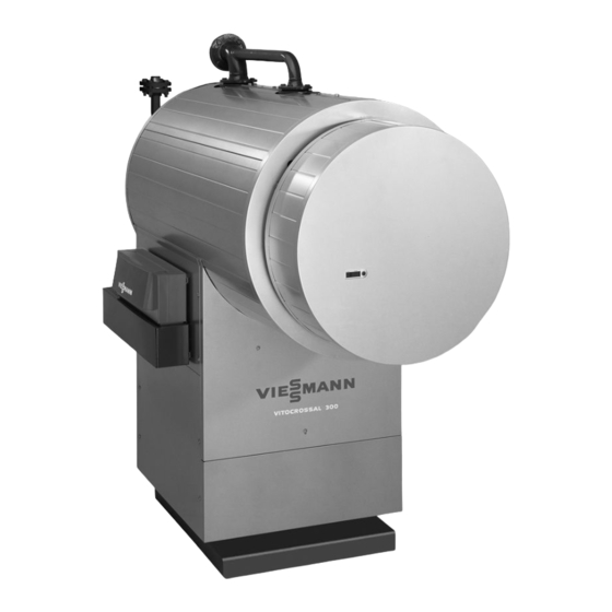
gas condensing boiler
Hide thumbs
Also See for VITOCROSSAL 300 Type CT3:
- Technical manual (48 pages) ,
- Installation instructions manual (32 pages) ,
- Operating instructions and user's information manual (12 pages)

Related Manuals for Viessmann VITOCROSSAL 300 Type CT3


Summary of Contents for Viessmann VITOCROSSAL 300 Type CT3
- Page 1 VIESMANN Service instructions for contractors Vitocrossal 300 Type CT3, 187 to 635 kW Gas condensing boiler For applicability, see the last page VITOCROSSAL 300 Please keep safe. 5692 909 GB 12/2011...
-
Page 2: Safety Instructions
Safety instructions Safety instructions Please follow these safety instructions closely to prevent accidents and mate- rial losses. Safety instructions explained ■ all current safety regulations as defined by DIN, EN, DVGW, TRGI, Danger TRF, VDE and all locally applicable This symbol warns against the standards, risk of injury. - Page 3 ■ When using gas as fuel, also close the For replacements, use only orig- main gas shut-off valve and safeguard inal spare parts from Viessmann against unauthorised reopening. or those which are approved by ■ Isolate the system from the power sup- Viessmann.
-
Page 4: Table Of Contents
Index Index Commissioning, inspection, maintenance Steps - commissioning, inspection and maintenance.......... Further details regarding the individual steps............Parts lists......................18 Commissioning/service reports................ 25 Specification....................... 26 Certificates Declaration of Conformity..................30 Certificates Manufacturer's certificate..................31 Keyword index....................32... -
Page 5: Commissioning, Inspection, Maintenance
Commissioning, inspection, maintenance Steps - commissioning, inspection and maintenance For further information regarding the individual steps, see the page indicated Commissioning steps Inspection steps Maintenance steps Page • 1. Checking the high limit safety cut-out setting..... • 2. Filling the heating system with water and venting..•... - Page 6 Commissioning, inspection, maintenance Steps - commissioning, inspection and… (cont.) Commissioning steps Inspection steps Maintenance steps Page • 22. Checking the flue system for leaks • • 23. Adjusting the burner............16 • 24. Instructing the system user........... 16 • 25. Operating and service documents........ 17...
-
Page 7: Further Details Regarding The Individual Steps
Commissioning, inspection, maintenance Further details regarding the individual steps Checking the high limit safety cut-out setting The high limit safety cut-out must not be Control unit installation and serv- set higher than 110 °C; if required, set it ice instructions to a maximum of 110 °C. -
Page 8: Minimising Pulsation Noise
Commissioning, inspection, maintenance Further details regarding the individual steps (cont.) 8. Check all gaskets and plugs, and Danger retighten if necessary. For safe operation, a minimum operating pressure of 0.5 bar is Note essential. We recommend you check all con- For this, a minimum pressure nections on the heating water side for switch can be used. -
Page 9: Shutting Down The System
Commissioning, inspection, maintenance Further details regarding the individual steps (cont.) 1. Undo nut A on lever B of rotary 3. Lock the rotary damper with nut A. damper C. 4. Re-adjust the burner if required. 2. Adjust the lever until all pulsation noise has ceased (the lever mirrors the damper position). -
Page 10: Cleaning The Combustion Chamber And Heating Surfaces
Commissioning, inspection, maintenance Further details regarding the individual steps (cont.) Cleaning the combustion chamber and heating surfaces Please note 2. Remove loose deposits from the Contact with unalloyed iron and boiler; flush the heating surfaces and scratches on parts in contact with the flue gas collector thoroughly with flue gases can lead to corrosion. -
Page 11: Checking All Connections And The Sensor Well On The Heating Water Side For Leaks
Commissioning, inspection, maintenance Further details regarding the individual steps (cont.) Checking all connections and the sensor well on the heating water side for leaks Danger 1. Remove cap A from the back of the There is a risk of injury when boiler. - Page 12 Commissioning, inspection, maintenance Further details regarding the individual steps (cont.) Pump-controlled pressure maintain- Diaphragm expansion vessel ing systems 1. Drain the system or close the cap Note valve on the diaphragm expansion Install a diaphragm expansion vessel vessel and reduce the pressure until (DEV) as individual boiler protection in the pressure gauge indicates "0".
-
Page 13: Checking The Flue Gas Collector For Leaks
Commissioning, inspection, maintenance Further details regarding the individual steps (cont.) Checking the flue gas collector for leaks 1. Traces of condensate on the outside 2. If required, retighten the gaskets at of the flue gas collector indicate a clamping clips A and at actuator leak. -
Page 14: Cleaning The Sight Glass In The Boiler Door
Commissioning, inspection, maintenance Further details regarding the individual steps (cont.) Cleaning the sight glass in the boiler door Check gaskets A and hose connection B for leaks. Closing the boiler door 1. Tighten the screws on the boiler door 2. Install the gas supply pipe and check evenly and diagonally. -
Page 15: Checking The Water Quality
Commissioning, inspection, maintenance Further details regarding the individual steps (cont.) Checking the water quality Enter the amount of top-up water and the total hardness of the feed and boiler water into the following table. For water quality requirements, see page 27. Meter read- Fill and top- Total water... -
Page 16: Adjusting The Burner
Commissioning, inspection, maintenance Further details regarding the individual steps (cont.) 1. To dewater the condensate drain, 5. Connect the line with a U-bend to the disconnect drain hose A. condensate drain and fill with water or fit a siphon and fill that with water. 2. -
Page 17: Operating And Service Documents
Commissioning, inspection, maintenance Further details regarding the individual steps (cont.) Operating and service documents 1. Complete and detach the customer registration card: ■ Hand system users their section for safekeeping. ■ Retain the heating contractor's section. 2. File all parts lists, operating and serv- ice instructions in the folder and hand this over to the system user. -
Page 18: Parts Lists
Parts lists Parts lists When ordering spare parts: 215 Side panel, top Quote the part no. and serial no. (see 216 Side panel, l.h. and r.h. type plate) and the position number of 217 Finned bottom panel, r.h. front the required part (as per this parts list). 220 Finned bottom panel, l.h. - Page 19 Parts lists Parts lists (cont.)
- Page 20 Parts lists Parts lists (cont.)
- Page 21 Parts lists Parts lists (cont.)
- Page 22 Parts lists Parts lists (cont.)
- Page 23 Parts lists Parts lists (cont.)
- Page 24 Parts lists Parts lists (cont.)
-
Page 25: Commissioning/Service Reports
Commissioning/service reports Commissioning/service reports Commissioning Service Service date: Service Service Service date: Service Service Service date: Service Service Service date: Service Service Service date:... -
Page 26: Specification
Specification Specification Rated heating output = 40/30 °C = 80/60 °C Rated heat input 234.5 385.5 Product ID CE-0085AQ0257 Flue gas parameters Temperature (at return temp. 30 °C) ■ at rated heating out- °C ■ at partial load °C Temperature (at return °C temp. -
Page 27: Water Quality Requirements
Water quality requirements Note Observing the following requirements is necessary to safeguard your warranty rights. The manufacturer's warranty excludes damage due to corrosion and scaling. Prevention of damage due to scaling Prevent excessive scale build-up (calcium carbonate) on the heating surfaces. For heating systems with operating temperatures up to 100 °C, the VDI Directive 2035 sheet 1 "Prevention of heating system damage –... - Page 28 Water quality requirements (cont.) ■ In systems > 50 kW, install a water ■ Commission the system step by step, meter to record the volume of the fill & starting with the lowest boiler output top-up water. Enter the volume of the and a high heating water flow rate.
- Page 29 Water quality requirements (cont.) Prevention of damage due to corrosion on the water side The corrosion resistance of ferrous The use of gas-permeable components, materials on the heating water side of e.g. plastic pipes that are not diffusion- heating systems and boilers depends on proof in underfloor heating systems, the absence of oxygen in the heating should be avoided.
-
Page 30: Certificates
Certificates Declaration of Conformity We, Viessmann Werke GmbH&Co KG, D-35107 Allendorf, declare as sole respon- sible body, that the product Vitocrossal 300, type CT3, 170-575 (187-635) kW ■ with the Vitotronic boiler control unit and ■ with the Vitotronic boiler control unit and MatriX radiant burner... -
Page 31: Certificates
Certificates Manufacturer's certificate We, Viessmann Werke GmbH&Co KG, D-35107 Allendorf, confirm that this product meets the conditions specified by the 1st German Immissions Order (BImSchV): ■ NO limits in accordance with para. 6 (1). ■ Flue gas loss of max. 9 % in accordance with para. 10 (1). -
Page 32: Keyword Index
Keyword index Keyword index Adjusting the burner......16 Heating system ■ Filling with water.......7 ■ Venting..........7 Boiler door High limit safety cut-out......7 ■ Closing..........14 ■ Opening..........9 Minimising pulsation noise....8 Checking connections on the heating water side for leaks......11 Neutralising system......9 Checking gaskets of the boiler door...10 Checking the diaphragm expansion ves- sel............11 Operating and service documents..17... - Page 36 7454012 7454013 7454014 7454027 7454028 7454029 7454030 7454031 7454032 Viessmann Werke GmbH&Co KG Viessmann Limited D-35107 Allendorf Hortonwood 30, Telford Telephone: +49 6452 70-0 Shropshire, TF1 7YP, GB Fax: +49 6452 70-2780 Telephone: +44 1952 675000 www.viessmann.com Fax: +44 1952 675040...
Need help?
Do you have a question about the VITOCROSSAL 300 Type CT3 and is the answer not in the manual?
Questions and answers