Table of Contents
Advertisement
Quick Links
Advertisement
Table of Contents

Related Manuals for Keys Fitness ST-IB


Summary of Contents for Keys Fitness ST-IB
- Page 1 Owner’s Manual International Bench Customer Service (888) 340-0482 4009 Distribution Drive Suite 250 Garland, TX 75041 www.keysfitness.com SERIAL TAG IS LOCATED ON THE FRAME Model Name: ST-IB Date of Purchase: Serial Number: 215-00219 08/07 Rev A...
-
Page 2: Table Of Contents
Table of Contents Important Safety Information Assembly Getting Started Hardware Identifier Assembly Steps Adjustments Seat Adjustments Backrest Adjustment Attachments Curl Bar Olympic Plate Adapter Arm Curl Post Weight Rests and Safety Spotters Warm Up Exercises Parts List Exploded Views Warranty... -
Page 3: Important Safety Information
Advanced: Complete 3 sets of 12 reps DISCLAIMER: Keys Fitness is not responsible for the misuse of any of its products or for any injury sustained while using any Keys Fitness product. The consumer uses any or all of Keys Fitness products at their own risk. -
Page 4: Assembly
Before assembling, the unit should be placed as close as possible to its final location. If you are missing any parts or hardware, please call Keys Fitness at 1-888-340- 0482. Tools have been provided to assist with product assembly. Keys Fitness recommends for two people to assemble the unit. -
Page 5: Hardware Identifier
Assembly Hardware Identifier See the drawings below to identify the hardware used in the assembly. The number in paren- theses is the reference number of the part. Note: Some hardware may be pre-installed in some parts. M8 x 10mm Set Screw (60) M4 x 16mm Screw (57) M10 Washer (43) -
Page 6: Assembly Steps
Assembly Step 1 Insert four M10X60mm carriage bolts (29) up through the bottom of the right stabilizer (2). Attach the right upright (4) to the right stabilizer (2) with indicated carriage bolts and nylon locknuts (58). Repeat to complete the assembly of the left stabilizer (1) and left upright (3). Note: Make sure the recessed areas around the holes on stabilizers are on the bottom. - Page 7 Assembly Step 2 Attach the crossbar (5) to the right upright (4) using two M10X120mm bolts (14), an upright plate (15), and two M10 nylon locknuts (58). Repeat to complete the assembly for the left upright (not shown). Figure 2 Step 3 Attach the right rear support (7) to the right stabilizer (2) using the indicated M10X60mm car- riage bolts (29), two washers (43), and two M10 nylon locknuts (58).
- Page 8 Assembly Step 4 Attach the front leg (12) to the front stabilizer (11) with two M10X95mm bolts (64) and two M10 nylon locknuts (58). Figure 4 Step 5 Position the frame (8) so that the hexagonal holes are on the bottom. Attach the frame (8) to the crossbar (5) using three M10X70mm bolts (33), two M10 washers (43), and three M10 nylon locknuts (58).
- Page 9 Assembly Step 6 Tighten the "T"-handle (45) into the seat carriage (42). Pull the "T"-handle (45) out as far as it will go and slide the seat carriage (42) onto the frame (8). Attach the front leg (12) to the frame (8) using two M8X60mm bolts (59), two M8X65mm bolts (46), six M8 washers (50), and four M8 nylon locknuts (49).
- Page 10 Assembly Step 8 Attach the tether on the seat adjustment pin (40) to the seat frame (10) using an M4X16mm screw (57). Attach the seat pad (21) to the seat frame (10) with four M6X20mm screws (41). Figure 8 Step 9 Attach the backrest pad (22) to the two backrest frames (17) with four M6X40mm screws (48) and four M6 washers (54).
- Page 11 Assembly Step 10 Apply a small amount of grease (included) to an M10X145mm bolt (53). Attach the seat frame (10) and the backrest frames (17) to the seat carriage (42) using the M10X145mm bolt (53), two M10 washers (43), and an M10 nylon locknut (58). Note: 1) The seat pad (21) has been removed from the drawing to clarify the installation to the seat carriage (42).
- Page 12 Assembly Step 12 Apply grease to the barrel of the M10X70mm bolt set (55). Next, attach the leg lever (18) to the front leg (12) and secure using the bolt set (55). Make sure the barrel of the bolt set (55) is inserted through both sides of the bracket on the front leg (12).
- Page 13 Assembly Step 14 Insert a weight rest (39) into the right upright (4) and secure by engaging the locking bar around the upright. Insert a safety spotter (27) into the right upright (4) and secure by engaging the locking bar around the upright.
- Page 14 Assembly Step 16 Attach a curl bumper (66) to curl bar (31) using a M4X16mm screw (57). Attach the curl bar (31) to the leg lever (18) and secure with the curl bar pin (28). Next, attach the tether on the curl bar pin (28) to the leg lever (18) using a M4X16mm screw (57). Step 17 Tighten all hardware from the previous steps using the appropriate tools.
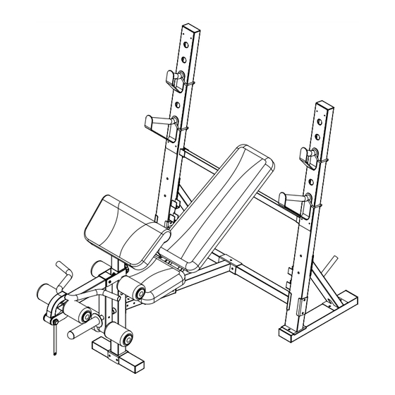
- Page 15 Assembly CONGRATULATIONS! You have completed assembly of your Strength Trainer International Bench.
-
Page 16: Adjustments
Adjustments Seat Adjustments To move the seat (21), loosen the "T"-handle (45) and pull it out as far as it will go. Slide the seat carriage (42) to the desired position and release the "T"-handle (45) back into the bench frame (8). -
Page 17: Attachments
Attachments Curl Bar Attachment Attach the curl bar (31) to the leg lever (18) and secure by inserting the curl bar pin (28). Note: You will need to remove the curl bar when using the leg extension. Olympic Plate Adapter To use olympic weights, press the 48mm round inner cap (38) into the olympic adapter (47). -
Page 18: Arm Curl Post
Attachments Arm Curl Post Remove the 64mm square inner cap (69) from front leg (12). Insert the curl post (13) into the front leg (12) and align the holes. Secure the curl post (13) with the curl post knob (56). Note: Make sure that the knob is fully tightened. -
Page 19: Warm Up Exercises
Warm Up Exercises... - Page 20 Warm Up Exercises...
- Page 21 Warm Up Exercises...
-
Page 22: Parts List
202-00775 19MM ROUND INNER CAP, ST-IB 206-00511 SQUARE BUSHING, ST-IB 219-00631 SAFETY SPOTTER, ST-IB 219-00632 Curl Bar Pin, ST-IB 202-00776 M10 x 60MM CARROAGE BOLT, ST-IB 202-00425 BOLT, M10X65 223-01232 CURL BAR, ST-IB 202-00773 25MM x 40MM INNER CAP, ST-IB... -
Page 23: Exploded Views
Exploded View... -
Page 24: Exploded View
Exploded View... -
Page 25: Warranty
Warranty Information PLEASE READ THESE WARRANTY TERMS AND CONDITIONS FULLY AND CAREFULLY BEFORE USING YOUR KEYS FITNESS EQUIPMENT. BY USING THE EQUIPMENT, YOU ARE CONSENTING TO BE BOUND BY THE FOLLOWING TERMS AND CONDITIONS. Frame: Lifetime Parts: 90 days Limited Warranty This Limited Warranty applies in the United States and Canada to Products manufactured or distributed by Keys Fitness Products, L.P. - Page 26 Notes...
- Page 27 Notes...
- Page 28 Customer Service (888) 340-0482 Keys Fitness Products 4009 Distribution Drive Suite 250 Garland, TX 75041...
Need help?
Do you have a question about the ST-IB and is the answer not in the manual?
Questions and answers