Advertisement
Quick Links
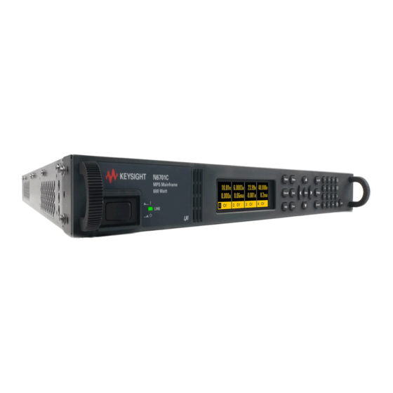
Front and Rear Panels at a Glance
1
- Display - Turns off after 1 hour of inactivity.
Press any key to restore the display.
2
- Navigation keys - Move the cursor to a menu item.
Press Select to select the highlighted item.
3
- Output keys - Turns the output on or off.
Enter voltage and current settings.
1
- GPIB - GPIB interface connector.
2
- Ground - Mchassis ground binding post.
3
- AC input - Requires a ground conductor.
4
- Output connector – Includes +/- output and
+/- sense terminals.
Additional Information
Built-in instrument help
Press the
Menu
key and scroll to the Help item.
Press Enter. Select a Help item from the menu.
Documentation for mobile devices
A manual for mobile devices is
available by scanning the following:
www.keysight.com
© Keysight Technologies 2016
Edition 1, October 2016
Printed In Malaysia
4
- On/Off switch and LED - LED indicates power is on.
Green: norrmal operation. Amber: screen saver mode.
5
- System keys - Toggle between 1- and 4- channel view.
Access front panel menu. Select an output channel.
6
- Numeric entry keys – Enter numeric values. Arrow keys
increment and decrement voltage and current settings.
5
- Digital Connector - Pins functions are user-configurable.
6
- USB – USB interface connector.
7
- LAN – 10/100 Base-T.
Left LED indicated activity
Right LED indicates link intergrity.
Documentation on the Web
Product documentation is available on the Web at
http://www.keysight.com/find/N6700.
Firmware updates
Install the latest firmware updates from the Web at
http://www.keysight.com/find/N6700firmware.
*5991-3422*
1. Remove the
blower cover.
Remove the screws
from the top and side
of the blower cover.
3. Install the
blower cover.
Carefully fit the spring
clips under the lip of
the power modules.
Connectors
have local
sense jumpers
installed
8A CONNECTOR
− − G +
+ +S G -S
5991-3422
Power Module Installation at a Glance
2. Install the
power
modules.
Align the module
over the pins and
push it down onto
the connector.
Install the screws
at each end of the
power module.
Output Connectors at a Glance
50 A CONNECTOR
12 A & 20 A
+
CONNECTOR
LOCKING
+S
+
-S
SCREW
50A SENSE
+S +LS -LS -S
Advertisement

Related Manuals for Keysight Technologies N6700C Series


Summary of Contents for Keysight Technologies N6700C Series
- Page 1 Documentation for mobile devices Firmware updates A manual for mobile devices is Install the latest firmware updates from the Web at available by scanning the following: http://www.keysight.com/find/N6700firmware. www.keysight.com 5991-3422 © Keysight Technologies 2016 *5991-3422* Edition 1, October 2016 Printed In Malaysia...
- Page 2 Front Panel Menu Reference Menu...
Need help?
Do you have a question about the N6700C Series and is the answer not in the manual?
Questions and answers