Table of Contents
Advertisement
Quick Links
Download this manual
See also:
User Manual
Advertisement
Table of Contents

Related Manuals for Nibe F2026


Summary of Contents for Nibe F2026
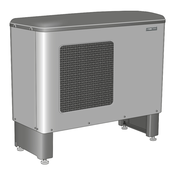
- Page 1 Installer manual NIBE™ F2026 Air/water heat pump IHB GB 1244-2 031865...
-
Page 3: Table Of Contents
Connecting accessories 11 Technical data 6 Commissioning and adjusting Dimensions and setting-out coordinates Preparations Sound pressure levels Filling and venting the heating medium sys- Technical specifications Electrical circuit diagram Balance temperature Stop temperature Item register NIBE™ F2026 Table of Contents |... -
Page 4: Important Information
Marking F2026 is CE marked and fulfils IP24. The CE marking means that NIBE ensures that the product meets all regulations that are placed on it based on relev- ant EU directives. The CE mark is obligatory for most products sold in the EU, regardless where they are made. -
Page 5: Inspection Of The Installation
Fuses property Safety breaker Earth circuit-breaker Heating cable type/effect Fuse size, heating cable (F3) Communication cable connected Miscellaneous Condensation water pipe Insulation condensation water pipe, thick- ness (if KVR 10 is not used) NIBE™ F2026 Chapter 1 | Important information... -
Page 6: Contact Information
Puh: 09-274 697 0 Fax: 09-274 697 40 E-mail: info@nibe.fi www.nibe.fi AIT France, 10 rue des Moines, 67000 Haguenau Tel : 03 88 06 24 10 Fax : 03 88 06 90 15 E-mail: info@nibe.fr www.nibe.fr NIBE Energy Systems Ltd, 3C Broom Business Park, Bridge Way, Chesterfield S41 9QG Tel: 0845 095 1200 Fax: 0845 095 1201 E-mail: info@nibe.co.uk www.nibe.co.uk... -
Page 7: Delivery And Handling
(see page Care must be exercised so that the heat pump is not scratched during installation. Do not place F2026 directly on the lawn or other non solid surface. NIBE™ F2026... - Page 8 The section of the pipe that can be affected by frost must be heated by the heating cable to prevent freezing. Route the pipe downward from F2026. The outlet of the condensation water pipe must be at a depth that is frost free or alternatively indoors (with reservation for local ordinances and regulations).
-
Page 9: Installation Area
The condensation water pipe must have a water trap to prevent air circulation in the pipe. Installation area The distance between F2026 and the house wall must be at least 350 mm. Clearance in front of F2026 should be at least one metre. utrymme Fritt utrymme framför NIBE™... -
Page 10: Supplied Components
Supplied components 2 flexible hoses (R25) with 4 seals Particle filterR25 Removing the covers Chapter 2 | Delivery and handling NIBE™ F2026... -
Page 11: The Heat Pump Design
3 The heat pump design General NIBE™ F2026 Chapter 3 | The heat pump design... - Page 12 Pipe connections XL 1 Connection, heating medium out of F2026, G1 (Ø28 mm) XL 2 Connection, heating medium in to F2026, G1 (Ø28 mm) XL 20 Service connection, high pressure XL 21 Service connection, low pressure XL 40 Connection, drip tray drain (Ø40 mm) Sensors etc.
-
Page 13: Electrical Cabinets
Terminal block, incoming supply Terminal block, external control voltage Terminal block, charge pump, external heating cable Terminal block, thermostat, communication, blocking compressor Terminal block, additional heat, downtime, com- mon alarm Terminal block, 4-way valve NIBE™ F2026 Chapter 3 | The heat pump design... -
Page 14: Pipe Connections
(does not apply current norms and directives. to docking with VVM 300/VVM 500). F2026 can only operate up to a return temperature of about 50 °C and an outgoing temperature of about 58 °C from the heat pump. -
Page 15: Pressure Drop, Heating Medium Side
Pressure drop, heating medium side F2026 -6, 8, 10 Tryckfall 6 kW 8, 10 kW Flöde 0,10 0,20 0,30 0,40 0,50 0,60 0,70 NIBE™ F2026 Chapter 4 | Pipe connections... -
Page 16: Docking Alternatives
Docking alternatives QM40 Shut-off valve RN10 Trim valve F2026 can be installed in several different ways. The re- Non-return valve quisite safety equipment must be installed in accordance EB101 Heat pump (F2026) with current regulations for all docked options. FL10 Safety valve, heat pump See www.nibe.eu for more docking options. - Page 17 Circulation pump, heating medium Auxiliary relay QM31 Shut-off valve, heating medium, supply QM32 Shut off valve, heating medium, return QN10 Reversing valve, hot water/heating medium QN26 Overflow valve Non-return valve RN10 Trim valve RN11 Trim valve NIBE™ F2026 Chapter 4 | Pipe connections...
-
Page 18: F2026 Docked With Vvm 300 (Floating Condensing)
F2026 (slave) can be connected to VVM 300 (master). F2026 is then controlled by VVM 300 and works with floating condensing to the heating system and prioritises hot water charging in VVM 300. -
Page 19: F2026 Docked With Vvm 500 (Floating Condensing)
VVM 500 F20XX F2026 (slave) can be connected to VVM 500 (master). F2026 is then controlled by VVM 500 and works with floating condensing to the heating system and prioritises hot water charging in VVM 500. If F2026 cannot supply the whole heating requirement the additional heat is supplied from VVM 500. - Page 20 F2026 docked to the electric/oil-fired/pellet boiler together with SMO 05 and water heater (floating condensing) -AA25 -FL2 -KA10 -CM1 -AA25 -EB1 -BT25 -QM31 -GP10 -CP11 -QN26 -AA25 -AA25-AA4 -QM32 -AA25 -AA25-BT1 -AA25-BT50 -BT7 -CP10 -FL11 -QN10 -EB101 -AA25 -FL10 -BT6...
- Page 21 F2026 docked to the electric/oil-fired/pellet boiler together with SMO 10 and water heater (floating condensing) -AA25 SMO 10 Oljepanna alternativt -KA3 elpanna med shunt -EM1 -FL2 -EP21 -QN25 -CM1 -CP1 -AA25 -EM1 -BT2 -GP10 -AA25-QN11 -BT52 -GP10 -AA25-BT2 -RN10 -BT3...
-
Page 22: F2026 Docked With Evc 13 (Floating Condensing)
F2026 during the set stop temperature. Hot water pro- duction only takes place using the existing hot water heater. The right curve is selected in EVC 13 so that F2026 is not disturbed. This option requires accessory RT 10. NOTE... -
Page 23: F2026 Docked To An Electric/Oil Boiler (Floating Condensing)
Additional heat can be blocked above the set balance temperature by means of the automatic control system in F2026. In other cases the heat pump does not collab- orate with the electric/oil fired boiler in the optimum way. Hot water production only takes place using the existing electric/oil boiler. - Page 24 F2026 docked with wood fired boiler and hot water heater (fixed condensing) -BT1 -AA25 -EB15 Extern alt. befintlig regler- utrustning. -EB100 -EM1 -RM1 -EB100 -FL10 -EB100 -BT34 -QM40 -HQ1 -RN10 -GP12 -QM1 F2026 charges the water heater/accumulator tank (EB15). When the firewood boiler is in use, the heat pump and...
-
Page 25: Electrical Connections
(UB3). Charge pump for F2026 can be connected to separate supply or to terminal block (X3). NOTE! If F2026 is not powered and the charge pump is connected to the terminal block (X3) there is a risk of freezing A common alarm can be connected to terminal (X6). -
Page 26: Connections
20 cm to high voltage cables when cable routing. Power connection Incoming supply cable is supplied and factory connected to the terminal block -X1. Approx. 1.8 m cable is access- ible outside the heat pump. Chapter 5 | Electrical connections NIBE™ F2026... -
Page 27: Connecting External Control Voltage
External heating cable (KVR 10) At connection of external control voltage you must con- F2026 is equipped with a terminal block for an external nect a switch (for tariff control) to connection X5:1 and heating cable (EB14, not supplied). The connection is X5:5 (compressor blocking) to prevent MP alarm. -
Page 28: Optional Connections
The following image displays the recommended cable routing from the electrical cabinet to the condensation water trough in F2026. The transfer from electrical cable to heating cable must occur after the lead-in to the con- densation water trough. The distance between the elec- trical cabinet and the lead-in to the condensation water trough is approx.1930 mm. -
Page 29: Connecting Accessories
Basic electrical circuit diagram for connection of auxiliary relays for additional heat and downtime. F2026 is equipped with a contact for external indication of common alarms. The function becomes active with all types of existing alarms. Max load on the relay contact is250V 2A. -
Page 30: Commissioning And Adjusting
Collar heater 2. Vent the system using the venting nipple on the en- closed flexible hose and possibly the circulation F2026 is equipped with a collar heater that heats the fan pump. collar when necessary (not activated on delivery). NOTE... -
Page 31: Start-Up And Inspection
1. Communication cable or thermostat, terminal block (X5) must not be connected. 2. Turn the isolator switch on. 3. Ensure that the F2026 is connected to the power source. 4. Check that the automatic protection (FB1) is on. 5. Check that the motor circuit-breaker (FC1) is on. -
Page 32: Adjustment, Charge Flow
ΔT will be 0.5 to 1 degrees lower (does during hot water charging or at high load. not apply to F2026-6 kW, which only has one fan speed). This is most easily done using the temperatures measured 1 and 4 flow temperature. -
Page 33: Control - Introduction
Plus button not need to have access to the controller. The plus button (S1) is used to browse through F2026 has an integrated return line sensor that limits the the channel system (forwards) or raise the value return temperature. of the selected parameter. -
Page 34: Display Explanation
The fan has two speeds, high or low (does not apply to Value: 01 F2026-6 kW that only have one fan speed). The fan is Shows the current value. Increase/decrease value using controlled by the ambient temperature. The lower speed the plus button respective minus button. -
Page 35: Control Conditions
It does not start counting again unless temperature in menu 5.9 which is used. the temperature is sufficiently high once again. B = Set temperature for cold outdoor air (channel A7). utelufttemp. Utelufttemperatur NIBE™ F2026 Chapter 7 | Control - Introduction... -
Page 36: Control Conditions Defrosting
After two minutes the com- pressor starts again (if the pressure has fallen), other- wise there is a constant high pressure alarm (alarm 06). 5. The temperature on the flow temperature sensor falls below 4 °C. Chapter 7 | Control - Introduction NIBE™ F2026... -
Page 37: Control - Channels
Shows the compressor status. address (1 – 9) for communication with SMO 10. Compressor off. For example 3 x F2026 in the same system are allocated Compressor on. the addresses 1, 2 and 3. The F2026 that produces hot Compressor blocked due to an alarm water should be set to 1. - Page 38 1 and 120 minutes. Factory setting 120 minutes. Stop temperature, the set ambient temperature value when the downtime relay is activated, F2026 stops. When the stop temperature is set between 0 and -20 °C the flow temperature is limited linearly to -7 °C / 58 °C to -20 °C / 50 °C (see diagram on page 45).
-
Page 39: Disturbances In Comfort
See the manual for the indoor module. NOTE High room temperature As F2026 can be connected to a large number External switch for changing the room heating activ- of external units, these should also be checked. ated. - Page 40 Short operations times Indicated as 16 in channel S1. Check the connection difference for the thermo- stat. Check the start temperature hot water in any NIBE indoor module. Check the charge flow and High pressure pressostat the particle filter which may be partially clogged.
- Page 41 6.18 2.84 4.348 1.587 5.37 2.67 3.583 1.426 4.69 2.50 2.968 1.278 4.10 2.33 2.467 1.136 2.068 1.007 1.739 0.891 1.469 0.785 1.246 0.691 1.061 0.607 0.908 0.533 0.779 0.469 0.672 0.414 NIBE™ F2026 Chapter 9 | Disturbances in comfort...
- Page 42 2.186 1.59 1.817 1.39 1.518 1.22 1.274 1.07 1.075 0.93 0.911 0.81 0.775 0.71 0.662 0.62 0.568 0.54 0.490 0.47 0.4233 0.41 0.367 0.36 0.320 0.32 0.280 0.28 0.245 0.25 0.216 0.22 Chapter 9 | Disturbances in comfort NIBE™ F2026...
-
Page 43: Accessories
Auxiliary relay Room thermostat Heating thermostat Hot water control Part no. 089 423 Part no. 418 366 Part no. 418 801 Shuttle valve, Cu-pipe Ø28 Max recommended charge power, 15 kW Part no. 089 152 NIBE™ F2026 Chapter 10 | Accessories... -
Page 44: Technical Data
11 Technical data Dimensions and setting-out coordinates 1075 1175 Ø 1200 utrymme Fritt utrymme framför Chapter 11 | Technical data NIBE™ F2026... -
Page 45: Sound Pressure Levels
The sound pressure levels are further affected by walls, Sound pressure levels bricks, differences in ground level, etc and should there- F2026 is usually placed next to a house wall, which gives fore only be seen as guide values. a directed sound distribution that should be considered. -
Page 46: Technical Specifications
Nominal flow (Min flow at defrosting.) 0.16 0.20 0.25 Internal pressure drop at nominal flow Max/Min heating medium temp continuous operation °C 58/20 Connection heating medium ext thread G1 (?28 mm) Dimensions and weight Width 1200 Chapter 11 | Technical data NIBE™ F2026... - Page 47 Max. permitted impedance in the mains connected point in accord- ance with EN 61000-3-11. Start currents can cause short voltage Working area During shorter time it is allowed to have lower working temperatures on the water side, e.g. during start up. NIBE™ F2026 Chapter 11 | Technical data...
-
Page 48: Electrical Circuit Diagram
Electrical circuit diagram Chapter 11 | Technical data NIBE™ F2026... - Page 49 NIBE™ F2026 Chapter 11 | Technical data...
- Page 50 Chapter 11 | Technical data NIBE™ F2026...
- Page 51 NIBE™ F2026 Chapter 11 | Technical data...
- Page 52 Chapter 11 | Technical data NIBE™ F2026...
-
Page 53: Item Register
12 Item register Item register F2026 docked with VVM 500 (floating condensing), 17 Accessories, 41 F2026 docked with wood fired boiler and hot water heater (fixed Additional heat / Downtime, 26 condensation), 22 Adjustment, charge flow, 30 Ambient temperature sensor, 26... - Page 54 List of components, 9–10 Sound pressure levels, 43 Thermostat control, 26 Start-up and inspection, 29 Transport and storage, 5 Status channels, 35 Troubleshooting, 37 Stop temperature, 28 Sensor placement, 38 Supplied components, 8 Chapter 12 | Item register NIBE™ F2026...
- Page 56 NIBE AB Sweden Hannabadsvägen 5 Box 14 SE-285 21 Markaryd info@nibe.se www.nibe.eu 031865...
Need help?
Do you have a question about the F2026 and is the answer not in the manual?
Questions and answers