
Related Manuals for Hameg HM8143


Summary of Contents for Hameg HM8143
- Page 1 99 Washington Street Melrose, MA 02176 Fax 781-665-0780 TestEquipmentDepot.com A r b i t r a r y P o w e r S u p p l y H M 8 1 4 3 Manual...
-
Page 2: Declaration Of Conformity
HAMEG instruments fulfi ll the regulations of the EMC directive. The 3. Infl uence on measuring instruments. conformity test made by HAMEG is based on the actual generic- and Under the presence of strong high frequency electric or magnetic fi elds, product standards. -
Page 3: Table Of Contents
C o n t e n t Deutsch English Declaration of Conformity General information regarding the CE-marking Arbitrary Power Supply HM8143 Specifi cations Important hints Symbols Unpacking Positioning Transport Storage Safety instructions Proper operating conditions Warranty and Repair Maintenance Mains voltage... -
Page 4: Arbitrary Power Supply Hm8143
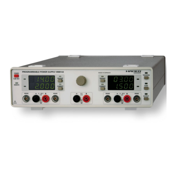
H M 8 1 4 3 A r b i t r a r y P o w e r S u p p l y H M 8 1 4 3 2x 0-30 V/0-2 A 5 V/0-2 A AF arbitrary signal Display resolution 10 mV /1 mA Arbitrary waveform power supply (1024 points, 12 bit) Tracking mode for 30 V outputs... -
Page 5: Specifi Cations
S p e c i f i c a t i o n s Inputs: Modulation input (BNC socket): 0-10 V Arbitrary Power Supply HM8143 Accuracy: 1 % of full scale Valid at 23 °C after a 30 minute warm-up period Modulations bandwidth (- 3 dB): ‹... -
Page 6: Important Hints
Do not disconnect the safety ground either inside or outside of the instrument! Two positions are possible: According to picture 1 the front feet are used to lift the instrument so its front points slightly upward. (Appr. 10 degrees) – The line voltage of the instrument must correspond to the line voltage used. If the feet are not used (picture 2) the instrument can be com- – Opening of the instrument is allowed only to qualified per- bined with many other HAmeG instruments. sonnel – Prior to opening the instrument must be disconnected from In case several instruments are stacked (picture 3) the feet rest the line and all other inputs/outputs. in the recesses of the instrument below so the instru-ments can not be inadvertently moved. Please do not stack more than In any of the following cases the instrument must be taken out 3 instruments. A higher stack will become unstable, also heat of service and locked away from unauthorized use: dissipation may be impaired. -
Page 7: Warranty And Repair
Types of fuses: Specifications with tolerances are valid after a 30 minute warm- up period and at 23 degrees C. Specifications without tolerances Size 5 x 20 mm; 250V~, STOP are typical values of an average instrument. IeC 60127-2/5 eN 60127-2/5 Warranty and Repair Line voltage Correct fuse type 230 V 2 x 1.6 A slow blow TiPP HAmeG instruments are subjected to a rigorous quality control. 115 V 2 x 3.2 A slow blow Prior to shipment each instrument will be burnt in for 10 hours. Intermittent operation will produce nearly all early failures. After burn in, a final functional and quality test is performed to check all operating modes and fulfilment of specifications. The latter is performed with test equipment traceable to na- tional measurement standards. Statutory warranty regulations apply in the country where the HAmeG product was purchased. In case of complaints please contact the dealer who supplied your HAmeG product. Maintenance The instrument does not require any maintenance. Dirt may be removed by a soft moist cloth, if necessary adding a mild detergent. (Water and 1 %.) Grease may be removed with ben-... -
Page 8: Controls And Display
4mm banana sockets CV (green LED) OUTPUT (pushbutton and LED) If the CV LED is lit, the HM8143 is in constant voltage mode. On/off key for all channels CC (red LED) If the CC LED is lit, the HM8143 is in constant current mode. -
Page 9: Basics Of Power Supplies
It is mandatory that the power supplies used are defi nitely specifi ed for these operating modes. This is the case with all OPVA HAMEG supplies. As a rule, the output voltages to be combined voltage are independent of each other, hence, it is allowed to connect reference voltage the outputs of one supply with those of another or more. -
Page 10: Current Limit
Example: socket with safety ground terminal or via an isolation trans- A load requires 12 V at 2.7 A. Each 30 V output of the HM8143 can former of protection class II. deliver 2 A. First set both channels to 12 V. Then connect both –... -
Page 11: Electronic Load
By virtue of the modulation inputs MODULATION R/L Please note the polarity of the load terminals: the the rear panel of HM8143, it can be also be used as a modula- red terminal is the positive, the black terminal is tion power amplifi... -
Page 12: Tracking
That means until the values of the output volta- Error messages ge or current limit of both channels have set to the minimum or maximum values. In case of a mal function the HM8143 will display an error mes- sage on the left display (channel I): Display Meaning... -
Page 13: Remote Control27
R e m o t e c o n t r o l Function: The voltage values sent back by the HM8143 are Remote control the programmed voltage values. Use the MUx com- mands to query the actual values. RI1 + RI2... -
Page 14: Arbitrary
Function: This command interrupts all functions of the values of channel II, if the outputs are activated or the nominal HM8143. The outputs are switched off, the voltages values are displayed of the outputs are offf. and currents are set to 0. - Page 15 R e m o t e c o n t r o l 50 ms 100 ms 200 ms 500 ms 10 s 20 s 50 s Example: It is wished to program the following waveform: 10.00 V 30.00 V 100 ms 25.67 V 200 us...
Need help?
Do you have a question about the HM8143 and is the answer not in the manual?
Questions and answers