Advertisement
Table of Contents
Advertisement
Table of Contents

Subscribe to Our Youtube Channel
Related Manuals for minkaAire San Francisco


Summary of Contents for minkaAire San Francisco
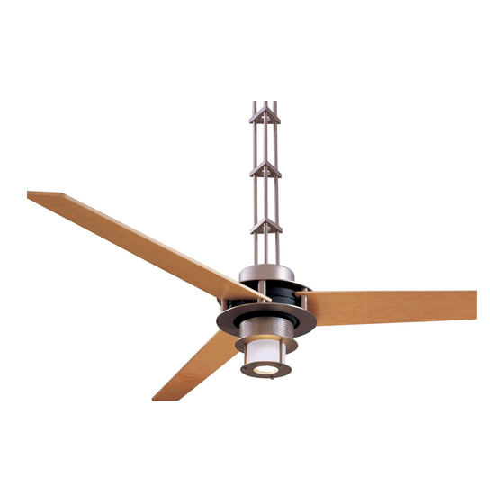
- Page 1 SAN FRANCISCO U.S. Patents: 5,951,253; 6,158,964; 6,171,060; 6,250,885 INSTRUCTION MANUAL WARRANTY CERTIFICATE...
- Page 2 This product is protected by United States Federal and/or State Law, including Patent, Trademark and/or Copyright laws. Manual design and all elements of manual design are protected by U.S. Federal and/or State Law, including Patent, Trademark and/or Copyright laws.
- Page 3 ® Minka-Aire warrants to the original owner that this fan will be free from defects in material and workmanship for one ® year from the date of purchase, excluding the motor. Minka-Aire warrants to the original owner that the motor in this fan shall be free from defects in material and workmanship for as long as the original purchaser owns the fan, and it remains in the original installation.
- Page 4 This warranty shall not apply to fans which have been damaged in any way, including improper installation, damage as a result of the removal of the fan from the origial installation, or damage in shipping. This warranty shall not apply to fans which have been subjected to use for which the fan was not designed.
-
Page 5: Table Of Contents
CONTENTS SAFETY FIRST ..................INSTALLING THE WALL TRANSMITTER..........PACKAGE CONTENTS ..............INSTALLING THE LIGHT KIT................. INSTALLING THE FAN..............OPERATING THE REMOTE CONTROL/ WALL TRANSMITTER... INSTALLING THE BLADES.............. MAINTENANCE ....................INSTALLING THE DOWNBRIDGE..........SPECIFICATIONS ..................... HANGING THE FAN................TROUBLESHOOTING ..................INSTALLING THE RECEIVER............ -
Page 6: Safety Rules
SAFETY RULES 1. Before you begin installing the fan, shut power off at the circuit breaker of the fuse box. 2. Be cautious! Read all instructions and safety information before installing your new fan. Review accompanying assembly diagrams. 3. Make sure that all electrical connections comply with local codes, ordinances, or National Electrical Codes. Hire a qualified electrician or consult a do-it-yourself wiring handbook if you are unfamiliar with installing electrical wiring. - Page 7 ATTENTION: The Energy Policy Act of 2005 requires this fan to be equipped with a 190 watt limiting device. If lamping exceeds 190 watts, the ceiling fan's light kit will shut off automatically. NOTE: The important safeguards and instructions appearing in this manual are not meant to cover all possible conditions and situations that may occur.
-
Page 8: Package Contents
PACKAGE CONTENTS Unpack your fan and check the contents. You should have the following items: 1. Fan Blades (3) A. Mounting Hardware: #10 x 2-1/2 screws (2 pcs.) 2. Mounting Bracket #8-32 x 3/4 machine screws (2 pcs.) 3. Downbridge Assembly Flat Washers (2 pcs.) 4. -
Page 9: Installing The Fan
INSTALLING THE FAN Tools Required: Phillips screw driver; slotted screw driver; step-ladder; wire cutters; electrical tape. PARALLEL WOOD BRACE CEILING (MIN. 2" THICK) MOUNTING OPTIONS JOIST OUTLET CROSS BRACE If there isn't an existing mounting box, then read the following instructions. Disconnect the power by removing fuses or turning off circuit breakers. -
Page 10: Installing The Blades
INSTALLING THE BLADES WARNING: All of the parts, hardware and components have been provided for your safety and the proper installation of your new ceiling fan. The ® use of other parts, hardware or components not supplied by Minka Aire with the fan will void the Minka Aire®... - Page 11 Step 5. (Fig. 9) Replace the Top Plate, align the "ARROW" labels from the Motor and Top Plate and secure with the six Allen Set Screws and Washers previously removed. CAUTION: Before tightening screws, make sure to pull blades straight out so that all blades are aligned the same. Tighten the Allen Set Screws making sure the blades sit flat over the Columns and also make sure that the top and bottom Columns are aligned straight with each other.Remove the "BLADE"...
-
Page 12: Installing The Downbridge
INSTALLING THE DOWNBRIDGE Step 1. (Fig. 10) Use the 1.5mm Allen Wrench to loosen the top and bottom Rod ties from the Downrod Bridge Assembly and carefully slide both Rodties next to the Rod tie in the center, lightly re-tighten the Allen Set Screws to keep them in place (do not over tighten the screws as this could scratch or damage the rod). - Page 13 CANOPY SWITCH COVER COUPLING COVER PLATE REVERSE SWITCH TOP& BOTTOM ACCESS SWITCH CUP RODTIES HOLE SCREW 1.5MM ALLEN "C"-CLIP REVERSE WRENCH SWITCH SWITCH CUP COVER SCREW SWITCH COVER COUPLING COVER PLATE SWITCH CUP Fig. 10 Fig. 11...
-
Page 14: Hanging The Fan
HANGING THE FAN MOUNTING BRACKET HEXNUT HANGING Step 1. (Fig 12) With the Canopy resting over the top Rodtie, raise the fan assembly and place the BRACKET Downrod Hanging Bracket inside the two arms in the Mounting Bracket and secure it with the Philips Screw and Hex Nut provided. -
Page 15: Installing The Receiver
INSTALLING THE RECEIVER WARNING: To avoid possible electrical shock be sure electricity is Step 2. Motor to Receiver Electrical Connections: Connect the WHITE turned off at the main fuse or breaker box before wiring. wire from the fan to the WHITE wire marked "TO MOTOR N" from the Receiver. - Page 16 Step 3. Receiver to House Supply Wires Electrical Connections: RECEIVER Connect the WHITE wire (Neutral) from the outlet box to the WHITE MOUNTING BRACKET wire marked "AC in N" from the receiver. Connect the BLACK wire TABS (Hot) from the outlet box to the BLACK wire marked "AC in L" from the receiver.
- Page 17 INPUT AC120V OUTLET BOX WHITE (NEUTRAL) BLACK (HOT) GREEN OR BARE WHITE AC SUPPLY COPPER (GROUND) BLACK ("AC IN L") BLACK WHITE ("AC IN N") RECEIVER BLACK ("TO MOTOR L") WHITE ("TO MOTOR N") ORANGE GROUND (CONNECT TO GROUND- GROUND WIRE ON (FOR UPPER LIGHT) (GREEN) HANGER BRACKE...
-
Page 18: Installing The Wall Transmitter
INSTALLING THE WALL TRANSMITTER WARNING! HOOK UP "IN SERIES" ONLY. DO NOT CONNECT NEUTRAL SUPPLY WIRE OF ELECTRIC CIRCUIT TO THE TRANSMITTER WALL SWITCH, DAMAGE TO THE TRANSMITTER WALL SWITCH AND POSSIBLE FIRE COULD OCCUR. Step 1. Remove the existing wall plate and switch from the wall outlet box. Step 2. -
Page 19: Installing The Light Kit
INSTALLING THE LIGHT KIT NOTE: Before starting installation, disconnect the power by turning off the circuit breaker or removing the fuse at fuse box. ATTENTION: The Energy Policy Act of 2005 requires this fan to be equipped with a 190 watt limiting device. - Page 20 OPERATING THE REMOTE CONTROL/WALL CONTROL Remote Control only: Install a A23 12 volt battery (included). To prevent damage to transmitter remove the battery if not used for long periods of time. Button: (Full Function Remote Control Restore Power to Ceiling Fan. instructions apply to ceiling fans that feature a DOWN Units Only) light (...
- Page 21 Warm Weather (forward) A DOWNWARD airflow creates a cooling effect as shown in Figure 20. This allows you to set your air conditioner on a warmer setting without affecting your comfort. Cool Weather (Reverse) An UPWARD airflow moves warmer air off the ceiling area as shown in Figure 21.
-
Page 22: Care Of Your Fan
CARE OF YOUR FAN 4. Use a lint free lightly damp cloth or duster to remove dust from Here are some suggestions to help maintain your fan. the blades. 1. Because of the fan's natural movement some connections may become 5. -
Page 23: Troubleshooting
TROUBLESHOOTING SYMPTOM SYMPTOM Fan Sounds Noisy Fan will not start SOLUTION SOLUTION Check to make sure the wall switch is turned on. Allow a 24-hour "break in" period. Most noises associated with a new fan will go away during this time. Check circuit fuses or breakers. - Page 24 SYMPTOM SYMPTOM Fan Wobble Lights shut off and will not come back on. SOLUTION SOLUTION NOTE: All blade sets are grouped by weight. Because wood and This unit is equipped with a wattage limiting device. Lamping in plastic blades vary in density, the fan may wobble even though excess of 190 watts will disable your ceiling fan’s light kit.
- Page 25 SYMPTOM Frequency Interference SOLUTION Turn the power off to your ceiling fan. Please use a small size tool to change the frequency settings on the control system. Return power to the unit. Note: After the AC power is on, do not press any other button on the transmitter before pressing the "Stop" button, doing so will cause the procedure to fail.
-
Page 26: Specifications
SPECIFICATIONS Fan Size Speed Volts Amps Watts RPM CFM N.W. G.W. C.F. These are typical readings. Your actual fan may vary. 0.36 2100 They do not include amps and wattage used by the 2.14' 56" Medium light(s). 0.47 3100 High 0.64 6100 For any additional information about your...
Need help?
Do you have a question about the San Francisco and is the answer not in the manual?
Questions and answers