
Subscribe to Our Youtube Channel
Related Manuals for minkaAire 52"


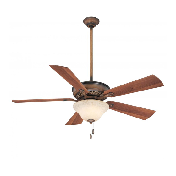
Summary of Contents for minkaAire 52"
- Page 1 Manual design and all elements of manual design are protected by U.S. Federal and/or State Law, including Patent, Trademark and/or Copyright laws.
- Page 2 ® Minka-Aire warrants to the original owner that this fan will be free from defects in material and workmanship for one ® year from the date of purchase, excluding the motor. Minka-Aire warrants to the original owner that the motor in this fan shall be free from defects in material and workmanship for as long as the original purchaser owns the fan, and it remains in the original installation.
- Page 3 This warranty shall not apply to fans which have been damaged in any way, including improper installation, damage as a result of the removal of the fan from the origial installation, or damage in shipping. This warranty shall not apply to fans which have been subjected to use for which the fan was not designed.
-
Page 4: Table Of Contents
CONTENTS SAFETY RULES................... ATTACHING THE FAN BLADES............PACKAGE CONTENTS..............LIGHT KIT INSTALLATION..............INSTALLING THE FAN..............OPERATING YOUR FAN................ HANGING THE FAN................ CARE OF YOUR FAN................ELECTRICAL CONNECTIONS............TROUBLESHOOTING................FINISHING THE INSTALLATION..........SPECIFICATIONS..................LISTED E75795 1151 W. Bradford Court, Corona, CA 92882 For Customer Assistance Call: 1-800-307-3267... -
Page 5: Safety Rules
SAFETY RULES 1. Before you begin installing the fan, shut power off at the circuit breaker of the fuse box. 2. Be cautious! Be cautious! Read all instructions and safety information before installing your new fan. Review accompanying assembly diagrams. 3. - Page 6 ATTENTION: ATTENTION: The Energy Policy Act of 2005 requires this fan to be equipped with a 190 watt limiting device. If lamping exceeds 190 watts, the ceiling fan's light kit will shut off automatically. NOTE: NOTE: The important safeguards and instructions appearing in this manual are not meant to cover all possible conditions and situations that may occur.
-
Page 7: Package Contents
PACKAGE CONTENTS Unpack your fan and check the contents. You should have the following items: 1. Fan blades (5) A. Mounting hardware: 2. Hanger bracket #10 x 1.5" Wood screws (2 PCs.) 3. Canopy #8 x 3/4" Machine screws (2PCs.) 4. -
Page 8: Installing The Fan
INSTALLING THE FAN Tools Required: Phillips screw driver; slotted screw driver; step-ladder; wire cutters; electrical tape. MOUNTING OPTIONS PARALLEL WOOD BRACE CEILING (MIN. 2" THICK) If there isn't an existing mounting box, then read the following instructions. Disconnect the CROSS JOIST BRACE OUTLET... -
Page 9: Hanging The Fan
HANGING THE FAN WARNING: WARNING: All of the parts, hardware and components such as the hanger Step 3. Remove the Hanger Ball from the Downrod Assembly by loosening bracket and hanger ball have been provided for your safety and the proper the Set Screw and removing the Cross Pin. - Page 10 DOWNROD CANOPY OUTLET BOX CROSS PIN DOWNROD SET SCREWS CANOPY COVER COUPLING HITCH PIN LOCK *OMIT COUPLING SET SCREWS COVER WHEN HANGER SET SCREW THE MINIMUM-LENGTH REGISTRATION SUPPLY BALL DOWNROD SLOT WIRES DOWNROD HANGER BRACKET Fig. 5 Fig. 6 Fig. 7 Fig.
-
Page 11: Electrical Connections
ELECTRICAL CONNECTIONS FAN CONTROLLED BY PULL CHAIN, LIGHT KIT CONTROLLED BY PULL CHAIN. HOUSE WIRE SUPPLY REMEMBER REMEMBER to shut the power off at the circuit breaker or fuse box. WHITE (NEUTRAL) GREEN (GROUND) BLACK (HOT) Follow the steps below to connect the fan to your house supply wires. Use the wire nuts supplied with your fan. - Page 12 FAN CONTROLLED BY PULL CHAIN, LIGHT KIT CONTROLLED BY WALL SWITCH. FAN CONTROLLED BY WALL CONTROL, LIGHT KIT CONTROLLED BY LIGHT SWITCH. HOUSE WIRE SUPPLY HOUSE WIRE SUPPLY WHITE (NEUTRAL) GREEN (GROUND) WHITE (NEUTRAL) GREEN (GROUND) BLACK (HOT) BLACK (HOT) CEILING CEILING LIGHT SWITCH...
-
Page 13: Finishing The Installation
FINISHING THE INSTALLATION Step 1. Remove 1 of the 2 screws from the bottom of the hanger bracket and loosen the other Outlet Box one half a turn from the screw head. Hanger Bracket Step 2. Slide the canopy up towards the hanger bracket and place the key hole on the canopy over the screw on the hanger bracket, turn canopy until it locks in place at the narrow section Screw of the key holes. -
Page 14: Attaching The Fan Blades
ATTACHING THE FAN BLADES Step 1. Attach the fan blades to the blade holders using the screws and fiber washers provided, tighten screws securely. (Fig. 15) SCREWS FIBER Step 2. Remove rubber stops from motor. Align WASHERS motor holes to blade holders and secure with FAN BLADE screws and lock washers provided, tighten FAN MOTOR... -
Page 15: Light Kit Installation
LIGHT KIT INSTALLATION NOTE: NOTE: Before starting installation, disconnect the power by turning off the circuit breaker or removing the fuse at fuse box. ATTENTION: ATTENTION: The Energy Policy Act of 2005 requires this fan to be equipped with a 190 watt limiting device. If lamping exceeds 190 watts, the ceiling fan's light kit will shut off automatically. - Page 16 LIGHT KIT BULBS LIGHT KIT MOUNTING PLATE CONNECTOR GLASS SHADE SCREWS SWITCH CUP LIGHT KIT PULL CHAIN MOUNTING RING METAL WASHER LIGHT KIT MOUNTING PLATE GLASS CAP SCREWS Fig. 17 Fig. 18 Fig. 19 FINIAL...
-
Page 17: Operating Your Fan
OPERATING YOUR FAN Restore power to ceiling fan and test for proper operation. Speed settings for warm or cool weather depend on factors such as the room size. Ceiling height, number of fans, etc. The Reverse switch is located on the switch cup. Slide the switch to the Left for warm weather operation. Slide the switch to the Right for cool weather operation. - Page 18 WINTER OPERATION SUMMER OPERATION Fig. 20 Fig. 21...
-
Page 19: Care Of Your Fan
CARE OF YOUR FAN Here are some suggestions to help maintain your fan. 4. Use a lint free lightly damp cloth or duster to remove dust from the blades. 1. Because of the fan's natural movement some connections may become 5. -
Page 20: Troubleshooting
TROUBLESHOOTING SYMPTOM SYMPTOM Fan will not start Fan Sounds Noisy SOLUTION SOLUTION Check fuses or circuit breakers. Allow a 24-hour "break-in" period. Most noises as sociated with a new fan go away during this time. Check line wire connections to fan and switch wire connections in switch housing. - Page 21 SYMPTOM SYMPTOM Fan Wobble Lights shut off and will not come back on. SOLUTION SOLUTION Check that all blade and blade holder screws are secured. This unit is equipped with a wattage limiting device. Lamping in excess of 190 watts will disable your ceiling fan’s light kit. To reset your light Use the enclosed blade balancing kit if blade wobble is excessive.
-
Page 22: Specifications
SPECIFICATIONS These are typical readings. Your actual fan may vary. Fan Size Speed Volts Amps Watts N.W. G.W. C.F. They do not include amps and wattage used by the 0.29 3610 light(s). 52" 9.80 11.95 2.59' Medium 0.44 5050 High 0.68 6720 For any additional information about your...
Need help?
Do you have a question about the 52" and is the answer not in the manual?
Questions and answers
green light comes on fan suddenly won't turn on
The 52" minkaAire fan may not turn on even when the green light is on due to the following reasons:
- Blown fuses or tripped circuit breakers.
- Loose line wire connections to the fan or switch wire connections in the switch housing.
- The reverse switch is in the middle position, preventing proper contact.
- Main power is off.
- Screws attaching the fan blade bracket to the motor hub are loose.
Check these areas to identify and fix the issue.
This answer is automatically generated
Own a Minka aire fan model # AC-552od. Can’t locate the manual. Need to know what the stated CFM is for this model. Thanks
The stated CFM for the MinkaAire fan model # AC-552OD is 6720.
This answer is automatically generated
What is the max wattage bulb i can use in the 52" Minka Aire Supra Oil Rubbed Bronze LED Ceiling Fan