Sony MV-101 Service Manual
Hide thumbs
Also See for MV-101:
- Operating instructions manual (37 pages) ,
- Installation/connections (4 pages) ,
- Product manual (2 pages)
Table of Contents
Advertisement
Quick Links
SERVICE MANUAL
Ver 1.2 2003.12
Copyrights
This product incorporates copyright protection
technology that is protected by method claims
of certain U.S. patents, other intellectual
property rights owned by Macrovision
Corporation, and other rights owners. Use of
this copyright protection technology must be
authorized by Macrovision Corporation, and is
intended for home and other limited viewing
uses only unless otherwise authorized by
Macrovision Corporation. Reverse engineering
or disassembly is prohibited.
Manufactured under license from Dolby
Laboratories. "Dolby", "Pro Logic", and the
double-D symbol are trademarks of Dolby
Laboratories. Confidential unpublished works.
Copyright 1998-1999 Dolby Laboratories. All
rights reserved.
"DTS," "DTS Digital Surround" and "DTS
Digital Out" are trademarks of Digital Theater
Systems, Inc.
Sony Corporation
9-877-353-03
2003L05-1
e Vehicle Company
C 2003.12
Published by Sony Engineering Corporation
Model Name Using Similar Mechanism
SPECIFICATIONS
System
Laser
Semiconductor laser
Signal format system
NTSC (US, E models)
PAL (AEP, UK, E models)
Audio characteristics
Frequency response
20 Hz to 20 kHz
Signal to noise ratio
90dB (A)
Hermonic distortion
0.03 %
Dynamic range
90dB
Wow and flutter
below measurable limits
(±0.001% W PEAK)
General
Outputs
Audio output
Video output
Optical output
Inputs
IR input
DV 12V input
Power requirements
12 V DC car battery
(negative ground)
Approx. 187 × 70 × 243 mm
Dimensions
× 2
1
7
(7
/
2
(w/h/d)
Mass
Approx. 2.1kg
(4 lb 11 oz)
0 °C to 45 °C
Operating temperature
(32 °F to 113 °F)
Supplied accessories
Parts for installation and
connections (1 set)
Card remote commander
RM-X135
Operating Instructions (1 set)
Design and specifications are subject to change
without notice.
MV-101
US Model
AEP Model
UK Model
E Model
NEW
× 9
5
/
/
in)
8
8
DVD PLAYER
Advertisement
Table of Contents

Related Manuals for Sony MV-101


Summary of Contents for Sony MV-101
-
Page 1: Dvd Player
Parts for installation and connections (1 set) Card remote commander RM-X135 Operating Instructions (1 set) Design and specifications are subject to change without notice. DVD PLAYER Sony Corporation 9-877-353-03 2003L05-1 e Vehicle Company C 2003.12 Published by Sony Engineering Corporation... -
Page 2: Table Of Contents
LINE WITH MARK 0 ON THE SCHEMATIC DIAGRAMS AND IN THE PARTS LIST ARE CRITICAL TO SAFE OPERATION. REPLACE THESE COMPONENTS WITH SONY PARTS WHOSE PART NUMBERS APPEAR AS SHOWN IN THIS MANUAL OR IN SUPPLEMENTS PUB- LISHED BY SONY. -
Page 3: Servicing Notes
MV-101 Ver 1.2 SERVICING NOTES For E model NTSC type and PAL type. About discs this player can The type of an NTSC system and the type of a PAL system exist in E model. play Please refer to the following figure about how to recognize. -
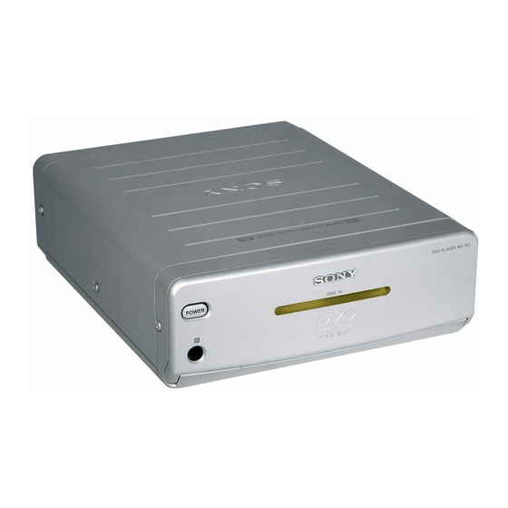
Page 4: General
MV-101 SECTION 1 This section is extracted from instruction manual. GENERAL Location of controls POWER DISC IN MV-101 POWER DISC IN RESET MV-101 1 POWER (on/off) button* * Warning when installing in a car To turn on/off the player, press and hold... - Page 5 To specify a desired point on a disc by wa VOL (–/+) buttons* chapter, title, or track. To turn up or down the volume. qa CLEAR button * These buttons work for optional Sony monitors other than XVM-R75 and XVM-H6.
- Page 6 MV-101 when XVM-R75, XVM-H6, or an optional monitor other than Sony product is connected. There is an R (audio right )/L (audio left)/V (video) output on MV-101, so you can connect either XVM- R70 or XVM-H65. XVM-R70...
- Page 7 MV-101 Horizontal installation Vertical installation ø 3 mm ø 3 mm Light sensor Light sensor Remote control sensor 15º 15º Wireless remote commander Almost 3 m (9.8 ft) Precautions Remote control sensor (4) •Choose the mounting location carefully. Before installing the remote control sensor, •Avoid installing the player in places:...
-
Page 8: Disassembly
MV-101 SECTION 2 DISASSEMBLY • This set can be disassembled in the order shown below. 2-1. DISASSEMBLY FLOW Note 1: The process described in can be performed in any order. Note 2: Without completing the process described in the next process can not be performed. -
Page 9: Cabinet (Rear)
MV-101 2-3. CABINET (REAR) 3 two screws 5 cabinet (rear) (+B2.6 × 6) 4 screw (+BTP3 × 6) 1 screw (+B2.6 × 6) 2 screw (+B2.6 × 6) 2-4. CASE (UPPER) 6 case (upper) 2 screw (+B2.6 × 6) 3 two bosses... -
Page 10: Dvd Md Assy
MV-101 2-5. DVD MD ASSY 5 tension spring (MD) C 1 power flexible board (CN2) 9 DVD MD assy 6 tension spring (MD) C 4 four tension spring (MD) B/D 7 tension spring (MD) A 2 two dampers (S) 3 two dampers (S) -
Page 11: Servo Board, Mechanism Deck
MV-101 2-7. SERVO BOARD, MECHANISM DECK qs mechanism deck 3 FFC-0.5-24 (CN11) 2 power flexible board qa servo board (CN1) 9 connector (CN102) 0 connector (CN302) 4 connector (CN301) 7 two screws (+B2.6 × 6) 5 four screws 1 wire (flat type) (+B2.6 ×... -
Page 12: Loading Mechanism Assy
MV-101 2-9. LOADING MECHANISM ASSY 2 loading mechanism assy 1 screw (+PTT2 × 4) 2-10. TRAVERSE MECHANISM ASSY 7 damper idle 8 traverse mechanism assy 1 two SCW-dampers 2 two SCW-dampers 4 damper idle 6 damper idle 5 damper idle... -
Page 13: Diagrams
MV-101 SECTION 3 DIAGRAMS 3-1. NOTE FOR PRINTED WIRING BOARDS AND SCHEMATIC DIAGRAMS • Circuit Boards Location Note on Printed Wiring Boards: Note on Schematic Diagram: • X : parts extracted from the component side. • All capacitors are in µF unless otherwise noted. pF: µµF power board •... -
Page 14: Printed Wiring Boards - Key Section
MV-101 3-2. PRINTED WIRING BOARDS – KEY Section – • :Uses unleaded solder. See page 13 for Circuit Boards Location. (Page 16) POWER BOARD KEY BOARD (SIDE A) CN101 • Semiconductor Location Ref. No. Location D103 G-13 D104 H-12 D105... -
Page 15: Schematic Diagrams – Key Section
MV-101 3-3. SCHEMATIC DIAGRAMS – KEY Section – • See page 13 for Waveform. CN101 C101 C102 C103 1000p +5V CPU R144 R102 P_DET A/D R103 CN102 C143 R128 R140 REMO_CBOX 100k R104 P_ON_CBOX IR_DATA R105 R136 P_CNT 5V_MAIN R106... -
Page 16: Printed Wiring Board - Power Section
MV-101 3-4. PRINTED WIRING BOARD – POWER Section – • See page 13 for Circuit Boards Location. :Uses unleaded solder. • Semiconductor Location SERVO BOARD Ref. No. Location POWER BOARD (SIDE A) F-13 G-10 H-12 H-12 H-12 F-13 D-13 D-13... -
Page 17: Schematic Diagram – Power Section
MV-101 3-5. SCHEMATIC DIAGRAM – POWER Section – • See page 18 for IC Block Diagrams. 2SA1037 TA78DL05AF B+ SWITCH 470k +5V REGULATOR 2.2k 0.01 RB411D-T106 0.047 +5V_CPU 100k 0.01 5.5V P_DET_A/D 0.01 0.01 REMO_CBOX P_ON_CBOX P_CNT REMO_BACK 100k (Page 15) - Page 18 MV-101 • IC Block Diagrams – POWER board – IC2 NJM2360AD 8 CD 7 SI 6 V+ CT OSC VREF 5 INVIN 1.25V – COMP IC3 LM2588T-12 SHUTDOWN CURRENT LIMIT, THERMAL LIMIT, UNDERVOLTAGE SHUTDOWN CONTROL DRIVER LOGIC STAGE CURRECTIV CURRENT...
-
Page 19: Exploded Views
Ver 1.2 SECTION 4 EXPLODED VIEWS NOTE: • -XX and -X mean standardized parts, so they • Items marked “*” are not stocked since they The components identified by mark 0 or dotted line with mark may have some difference from the original are seldom required for routine service. -
Page 20: Cabinet Front Assy Section
MV-101 4-2. CABINET FRONT ASSY SECTION not supplied (led board) not supplied Ref. No. Part No. Description Remark Ref. No. Part No. Description Remark A-3337-875-A LID (DVD) ASSY 3-255-480-01 BUTTON (EJECT) (Z) 3-255-481-01 BUTTON (POWER) 3-255-492-01 SPRING (LID) 3-255-483-01 WINDOW (IR) -
Page 21: Case (Lower) Assy Section
MV-101 4-3. CASE (LOWER) ASSY SECTION dvd md assy section not supplied Ref. No. Part No. Description Remark Ref. No. Part No. Description Remark 3-255-477-01 CASE (LOW) 3-255-497-01 SPRING (MD) (D), TENSION 3-225-807-12 DAMPER (S) 1-689-012-11 POWER FLEXIBLE BOARD 1-689-013-11 KEY FLEXIBLE BOARD... -
Page 22: Dvd Md Assy Section
MV-101 Ver 1.1 4-4. DVD MD ASSY SECTION mechanism deck section-1 Ref. No. Part No. Description Remark Ref. No. Part No. Description Remark X-3383-814-2 ESCUTCHEON ASSY 7-685-532-19 SCREW +B 2.6X5 X-3383-813-2 CHASSIS (MD) ASSY 7-685-546-14 SCREW +B 3X8 3-223-913-11 LABEL (OP CAUTION) (AEP, E) -
Page 23: Mechanism Deck Section-1
MV-101 4-5. MECHANISM DECK SECTION-1 mechanism deck section-2 CN302 CN102 not supplied CN301 CN101 CN103 CN601 Ref. No. Part No. Description Remark Ref. No. Part No. Description Remark 9-885-037-60 SERVO BOARD, COMPLETE * CN301 1-564-720-11 PIN, CONNECTOR (SMALL TYPE) 4P... -
Page 24: Mechanism Deck Section-3
MV-101 4-6. MECHANISM DECK SECTION-2 mechanism deck section-3 Ref. No. Part No. Description Remark Ref. No. Part No. Description Remark 9-885-036-31 TD-S-TOP-COVER 9-885-036-22 LOADING MECHANISM ASSY 9-885-036-24 SW BOARD, COMPLETE 9-885-036-28 LOADING BELT-L 9-885-036-43 SCREW (N), M1.7X1.5 7-685-781-09 SCREW +PTT 2X4 (S) - Page 25 MV-101 4-7. MECHANISM DECK SECTION-3 The components identified by mark 0 or dotted line with mark 0 are critical for safety. Replace only with part number specified. Ref. No. Part No. Description Remark Ref. No. Part No. Description Remark 9-885-036-25 SENSOR BOARD, COMPLETE 9-885-036-32 FFC-0.5-24 CORE L70...
-
Page 26: Electrical Parts List
MV-101 SECTION 5 ELECTRICAL PARTS LIST NOTE: • Due to standardization, replacements in the • Items marked “*” are not stocked since they The components identified by 0 or dotted line with mark mark parts list may be different from the parts speci- are seldom required for routine service. - Page 27 MV-101 POWER Ref. No. Part No. Description Remark Ref. No. Part No. Description Remark R117 1-216-845-11 METAL CHIP 100K 1/10W < CAPACITOR/SHORT > R118 1-216-845-11 METAL CHIP 100K 1/10W 1-107-910-11 ELECT 100uF R119 1-216-845-11 METAL CHIP 100K 1/10W 1-107-906-11 ELECT...
- Page 28 MV-101 POWER Ref. No. Part No. Description Remark Ref. No. Part No. Description Remark 1-162-927-11 CERAMIC CHIP 100PF 1-216-295-00 SHORT CHIP 1-162-920-11 CERAMIC CHIP 27PF 1-216-295-00 SHORT CHIP 1-456-538-11 COIL, CHOKE 130mH < CONNECTOR > < TRANSISTOR > * CN1...
- Page 29 MV-101 Ver 1.2 SENSOR SERVO Ref. No. Part No. Description Remark Ref. No. Part No. Description Remark 9-885-036-25 SENSOR BOARD, COMPLETE *********************** For the parts on SENSOR board, replace the entire mounted board. ************************************************************** 9-885-037-60 SERVO BOARD, COMPLETE ********************** < CONNECTOR >...
- Page 30 MV-101 Ver 1.2 Ref. No. Part No. Description Remark Ref. No. Part No. Description Remark PARTS FOR INSTALLATION AND CONNECTIONS ************************************** 1-827-344-12 CORD, CONNECTION (POWER) 1-824-336-11 CORD, CONNECTION (RCA) F902 1-478-064-11 RAY-CATCHER UNIT, INFRARED RAY (AEP, UK, E: PAL TYPE)
-
Page 31: Revision History
MV-101 REVISION HISTORY Clicking the version allows you to jump to the revised page. Also, clicking the version at the upper right on the revised page allows you to jump to the next revised page. Ver. Date Description of Revision 2003.05...
Need help?
Do you have a question about the MV-101 and is the answer not in the manual?
Questions and answers