Table of Contents
Advertisement
Quick Links
Advertisement
Table of Contents

Subscribe to Our Youtube Channel
Related Manuals for Supermicro A2SDi-H-TF


Summary of Contents for Supermicro A2SDi-H-TF
- Page 1 A2SDi-H-TP4F/TF USER’S MANUAL Revision 1.0...
- Page 2 State of California, USA. The State of California, County of Santa Clara shall be the exclusive venue for the resolution of any such disputes. Supermicro's total liability for all claims will not exceed the price paid for the hardware product.
- Page 3 It provides information for the installation and use of the A2SDi-H-TP4F/TF motherboard. About This Motherboard The Supermicro A2SDi-H-TP4F/TF motherboard comes with an integrated Intel® Atom SoC C3000 series (FCBGA1310) that has up to 16 Cores, a TDP of 32W and is optimized for low-power consumption.
- Page 4 A2SDi-H-TP4F/TF User's Manual Contacting Supermicro Headquarters Address: Super Micro Computer, Inc. 980 Rock Ave. San Jose, CA 95131 U.S.A. Tel: +1 (408) 503-8000 Fax: +1 (408) 503-8008 Email: marketing@supermicro.com (General Information) support@supermicro.com (Technical Support) Website: www.supermicro.com Europe Address: Super Micro Computer B.V.
-
Page 5: Table Of Contents
Preface Table of Contents Chapter 1 Introduction 1.1 Checklist ..........................8 Quick Reference .......................12 Quick Reference Table ......................13 Motherboard Features .......................15 1.2 Processor Overview ......................19 1.3 Special Features ........................19 Recovery from AC Power Loss ..................19 1.4 System Health Monitoring ....................20 Onboard Voltage Monitors ....................20 Fan Status Monitor with Firmware Control ...............20 Environmental Temperature Control .................20 System Resource Alert......................20... - Page 6 A2SDi-H-TP4F/TF User's Manual 2.5 Rear I/O Ports ........................28 2.6 Front Control Panel ......................32 2.7 Connectors .........................36 Power Connections ......................36 Headers ..........................37 2.8 Jumper Settings .........................45 How Jumpers Work ......................45 2.9 LED Indicators ........................49 Chapter 3 Troubleshooting 3.1 Troubleshooting Procedures ....................52 Before Power On ......................52 No Power ..........................52 No Video ...........................53...
- Page 7 Preface 4.6 Security ..........................88 4.7 Boot ............................92 4.8 Save & Exit .........................94 Appendix A BIOS Codes Appendix B Software Installation B.1 Installing Software Programs .....................98 B.2 SuperDoctor 5 ........................99 ® Appendix C Standardized Warning Statements Battery Handling ......................100 Product Disposal ......................102 Appendix D UEFI BIOS Recovery...
-
Page 8: Chapter 1 Introduction
• Product safety info: http://www.supermicro.com/about/policies/safety_information.cfm • If you have any questions, please contact our support team at: support@supermicro.com This manual may be periodically updated without notice. Please check the Supermicro website for possible updates to the manual revision level. - Page 9 Chapter 1: Introduction Figure 1-1. A2SDi-H-TP4F Motherboard Image Note: All graphics shown in this manual were based upon the latest PCB revision available at the time of publication of the manual. The motherboard you received may or may not look exactly the same as the graphics shown in this manual.
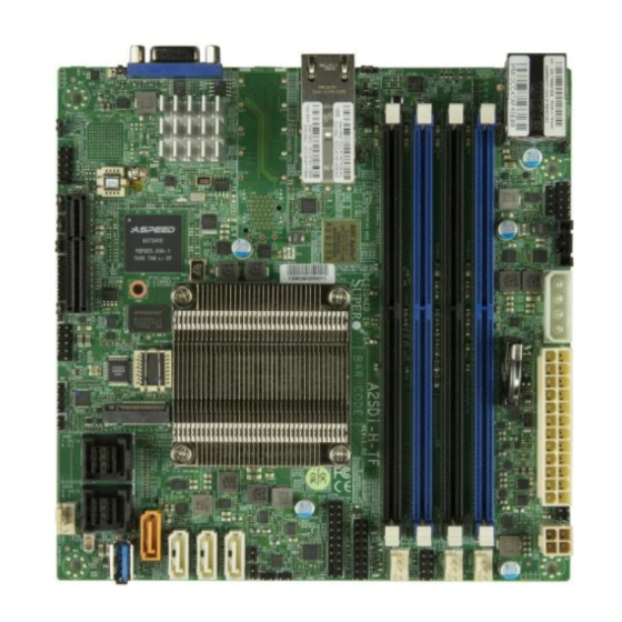
- Page 10 A2SDi-H-TP4F/TF User's Manual Figure 1-2. A2SDi-H-TF Motherboard Image...
- Page 11 Chapter 1: Introduction Figure 1-3. A2SDi-H-TP4F/TF Motherboard Layout (not drawn to scale) PRESS FIT JPTG1 JWD1 JPG1 Intel COM1 X557-AT2 IPMI LAN USB0/1 SRW2 LAN1 LAN2 LEDM1 LAN3 AST2400 LAN4 SRW1 JBT1 Intel SoC FCBGA1310 JMD1 M.2:PCI-E 3.0 X2 / I-SATA JSAS2 I-SATA 8-11...
-
Page 12: Quick Reference
A2SDi-H-TP4F/TF User's Manual Quick Reference LAN1 LEDM1 LAN3 LAN2 IPMI LAN LAN4 JWD1 USB0/1 UIDLED1 JPTG1 PRESS FIT JPTG1 JWD1 JPG1 JPG1 Intel COM1 X557-AT2 JBR1 COM1 IPMI LAN USB0/1 SRW2 JGP1 SRW2 LAN1 LAN2 LEDM1 JSMB1 JI2C1 JI2C2 LAN3 AST2400 LAN4 JPI2C1... -
Page 13: Quick Reference Table
Chapter 1: Introduction Quick Reference Table Jumper Description Default Setting JBR1 BIOS Recovery Pins 1-2 (Normal) JBT1 CMOS Clear Open (Normal) C1/JI SMB to PCI-E Slots Enable/Disable Pins 2-3 (Disabled) JPG1 VGA Enable/Disable Pins 1-2 (Enabled) JPME2 ME Manufacturing Mode Pins 1-2 (Normal) JPTG1 10Gb Ethernet Enable for LAN1/2/3/4... - Page 14 A2SDi-H-TP4F/TF User's Manual Connector Description LAN1/LAN2 : 10GBaseT LAN (RJ45) Ports LAN1 - LAN4 LAN3/LAN4 : 10G LAN (SFP+) Ports (TP4F only) SLOT7 CPU PCI-E 3.0 x4 Slot SRW1, SRW2 M.2 Mounting Screws Unit ID Button USB0/1 Back panel USB 2.0 Ports USB2/3 Front Accessible USB 2.0 Header USB4...
-
Page 15: Motherboard Features
Chapter 1: Introduction Motherboard Features Motherboard Features • Intel® Atom SoC C3000 series (FCBGA1310) processor Memory • Up to 256GB RDIMM or 64GB UDIMM DDR4 ECC/Non ECC with speeds of up to 2400MHz DIMM Size • Up to 32GB at 1.2V Expansion Slots •... - Page 16 A2SDi-H-TP4F/TF User's Manual Motherboard Features Power Management • Main switch override mechanism • Power-on mode for AC power recovery • ACPI power management • S5 support • Wake-on-Ring, Wake-on-LAN • Management Engine (ME) System Health Monitoring • Onboard voltage monitoring for +3.3V, 3.3V Standby, +5V, +5V Standby, +12V, VBAT, Memory, SoC Temp., System Temp., Memory Temp.
- Page 17 CPU TDP sizing. Note 2: For IPMI configuration instructions, please refer to the Embedded IPMI Con- figuration User's Guide available at http://www.supermicro.com/support/manuals/. Note 3: It is strongly recommended that you change BMC log-in information upon initial system power-on.
- Page 18 A2SDi-H-TP4F/TF User's Manual Figure 1-4. System Block Diagram GIGALAN RGMII2 RJ45 RTL8211F AST2400 COM1 HEADER TPM1.2 Header SVID HSIO[14] VR13 USB2.0[0] LPC PCIe 3.0_x4 PCIEX1 PCIE SLOT X4 HSIO[3.0] 8GT/s DDR4 (CHA) PCIEX4 DIMMA1,A2 PCIe 3.0_x2 2400/2133/1866MHz HSIO[13:12] M.2 2280/2242 8GT/s Intel SATA...
-
Page 19: Processor Overview
Chapter 1: Introduction 1.2 Processor Overview Built upon the functionality and capability of the Intel® Atom SoC C3000 series processor, the A2SDi-H-TP4F/TF motherboard offers maximum I/O expandability, energy efficiency, and data reliability in a 14-nm process architecture, and is optimized for embedded storage solutions The A2SDi-H-TP4F/TF supports the following features: •... -
Page 20: System Health Monitoring
A2SDi-H-TP4F/TF User's Manual 1.4 System Health Monitoring This section describes the health monitoring features of the A2SDi-H-TP4F/TF motherboard. The motherboard has an onboard Baseboard Management Controller (BMC) chip that supports system health monitoring. Once a voltage becomes unstable, a warning is given or an error message is sent to the screen. -
Page 21: Power Supply
Chapter 1: Introduction In addition to enabling operating system-directed power management, ACPI also provides a generic system event mechanism for Plug and Play and an operating system-independent interface for configuration control. ACPI leverages the Plug and Play BIOS data structures while providing a processor architecture-independent implementation that is compatible with Windows 8/R2, and Windows 2012/R2 operating systems. -
Page 22: Advanced Power Management
A2SDi-H-TP4F/TF User's Manual 1.8 Advanced Power Management The following new advanced power management features are supported by the motherboard. Management Engine (ME) The Management Engine, which is an ARC controller embedded in the IOH (I/O Hub), provides Server Platform Services (SPS) to your system. The services provided by SPS are different from those provided by the ME on client platforms. -
Page 23: Chapter 2 Installation
Chapter 2: Installation Chapter 2 Installation 2.1 Static-Sensitive Devices Electrostatic Discharge (ESD) can damage electronic com ponents. To prevent damage to your motherboard, it is important to handle it very carefully. The following measures are generally sufficient to protect your equipment from ESD. Precautions •... -
Page 24: Motherboard Installation
A2SDi-H-TP4F/TF User's Manual 2.2 Motherboard Installation All motherboards have standard mounting holes to fit different types of chassis. Make sure that the locations of all the mounting holes for both the motherboard and the chassis match. Although a chassis may have both plastic and metal mounting fasteners, metal ones are highly recommended because they ground the motherboard to the chassis. -
Page 25: Installing The Motherboard
Chapter 2: Installation Installing the Motherboard 1. Install the I/O shield into the back of the chassis. 2. Locate the mounting holes on the motherboard. See the previous page for the location. 3. Locate the matching mounting holes on the chassis. Align the mounting holes on the motherboard against the mounting holes on the chassis. -
Page 26: Memory Support And Installation
A2SDi-H-TP4F/TF User's Manual 2.4 Memory Support and Installation Note: Check the Supermicro website for recommended memory modules. Important: Exercise extreme care when installing or removing DIMM modules to pre- vent any possible damage. Memory Support The A2SDi-H-TP4F/TF supports up to 256GB RDIMM or 64GB UDIMM DDR4 ECC/Non ECC with speeds of up to 2400MHz. -
Page 27: Dimm Installation
Chapter 2: Installation DIMM Installation PRESS FIT JPTG1 1. Insert DIMM modules in the following JWD1 JPG1 Intel COM1 X557-AT2 order: DIMMA1, DIMMB1, then DIMMA2, IPMI LAN USB0/1 SRW2 DIMMB2. For the system to work properly, LAN1 LAN2 LEDM1 please use memory modules of the same LAN3 AST2400 LAN4... -
Page 28: Rear I/O Ports
A2SDi-H-TP4F/TF User's Manual 2.5 Rear I/O Ports See Figure 2-2 below for the locations and descriptions of the various I/O ports on the rear of the motherboard. PRESS FIT JPTG1 JWD1 JPG1 Intel COM1 X557-AT2 IPMI LAN USB0/1 SRW2 LAN1 LAN2 LEDM1 LAN3... - Page 29 VGA display. LAN Ports The A2SDi-H-TP4F has four 10Gb LAN ports, and the A2SDi-H-TF has two. These ports are located on the I/O back panel and accept RJ45 cables. There is also a dedicated IPMI LAN port on the I/O back panel.
- Page 30 A2SDi-H-TP4F/TF User's Manual Universal Serial Bus (USB) Ports There are two USB ports (USB0/1) on the I/O back panel. The motherboard also has one front access USB 2.0 header (USB2/3) and one USB 3.0 Type A header (USB4). The onboard headers can be used to provide front side USB access with a cable (not included).
- Page 31 Chapter 2: Installation COM Header There is one COM header (COM1) on the motherboard. COM Header Header Pin Definitions Pin# Definition Pin# Definition PRESS FIT Ground JPG1 Intel COM1 X557-AT2 SRW2 LEDM1 LAN3 AST2400 LAN4 1. COM1 PRESS FIT JPTG1 JWD1 JPG1 Intel...
-
Page 32: Front Control Panel
JF1 contains header pins for various buttons and indicators that are normally located on a control panel at the front of the chassis. These connectors are designed specifically for use with Supermicro chassis. See the figure below for the descriptions of the front control panel buttons and LED indicators. - Page 33 Chapter 2: Installation Power LED The Power LED connection is located on pins 15 and 16 of JF1. Refer to the table below for pin definitions. Power LED Pin Definitions (JF1) Pins Definition +3.3V Ground HDD LED The HDD LED connection is located on pins 13 and 14 of JF1. Attach a cable here to indicate the status of HDD-related activities, including IDE and SATA activities.
- Page 34 A2SDi-H-TP4F/TF User's Manual Reset Button The Reset Button connection is located on pins 3 and 4 of JF1. Attach it to a hardware reset switch on the computer case to reset the system. Refer to the table below for pin definitions. Reset Button Pin Definitions (JF1) Pins...
- Page 35 Chapter 2: Installation Overheat (OH)/Fan Fail LED Connect an LED cable to OH/Fan Fail connections on pins 7 and 8 of JF1 to provide warnings for chassis overheat/fan failure. Refer to the table below for pin definitions. OH/Fan Fail LED OH/Fan Fail Indicator Pin Definitions (JF1) Status...
-
Page 36: Connectors
A2SDi-H-TP4F/TF User's Manual 2.7 Connectors JBT1 Power Connections Intel SoC FCBGA1310 Main ATX Power, 4-pin HDD Power, 4-pin DC Power JPTG1 The primary power supply connector (JPW1) meets the ATX SSI EPS 24-pin specification. / I-SATA JWD1 JPH1 is a 4-pin power connector for HDD devices. JPV1 is the 12V DC power connector that provides alternative power for special enclosure when the 24-pin ATX power is not in use ATX Power 24-pin Connector Pin Definitions... -
Page 37: Headers
Chapter 2: Installation Headers Fan Headers There are four 4-pin fan headers on the motherboard. Pins 1-3 are backward compatible with traditional 3-pin fans. The onboard fan speeds are controlled by Thermal Management (via Hardware Monitoring) in the BIOS. When using Thermal Management setting, please use all 3-pin fans or all 4-pin fans. - Page 38 A2SDi-H-TP4F/TF User's Manual General Purpose I/O Header JGP1 is a general purpose input/ouput header via the Intel PCH. Refer to the table below for pin definitions. JGP1 Header Pin Definitions Pin# Definition Ground Ground GPP_E0 GPP_F1 GPP_E1 GPP_F2 GPP_E2 GPP_F3 GPP_F0 GPP_F4 1.
- Page 39 It enables the motherboard to deny access if the TPM associated with the hard drive is not installed in the system. Refer to the table below for pin definitions. Note: Please go to the following link for information on TPM: http://www.supermicro. com/manuals/other/TPM.pdf Trusted Platform Module Header...
- Page 40 A2SDi-H-TP4F/TF User's Manual Disk On Module Power Connector The Disk On Module (DOM) power connector at JSD1 provides 5V power to a solid-state DOM storage device connected to one of the SATA ports. Refer to the table below for pin definitions.
- Page 41 Chapter 2: Installation Power SMB (I C) Header Power System Management Bus (I C) header at JPI C1 monitors the power supply, fan and system temperatures. Refer to the table below for pin definitions. Power SMB Header Pin Definitions Pin# Definition Clock Data...
- Page 42 A2SDi-H-TP4F/TF User's Manual LAN Port Activity LED Headers JTGLED1 is the activity LED header for LAN3 and LAN4. LAN Activity LED Pin Definitions Pin# Definition +3.3V LAN3_ACT_N +3.3V LAN4_ACT_N JRT3 and JRT4 JRT3 is the thermal diode 1 header, and JRT4 is the thermal diode 2 header. They are thermal sensor headers that provide additional system temperature monitoring.
- Page 43 The A2SDi-H-TP4F/TF has twelve SATA 3.0 ports that are supported by the SoC. I-SATA0 has built-in power pins to support Supermicro's SATA DOM (Disk On Module) solutions. I-SATA ports 4-11 are available via miniSAS. JMD1 is an M.2 PCI-E 3.0 X2 slot that is MUX with I-SATA.
- Page 44 Note: UID can also be triggered via IPMI on the motherboard. For more information on IPMI, please refer to the IPMI User's Guide posted on our website at http://www. supermicro.com. UID Switch UID LED Pin Definitions...
-
Page 45: Jumper Settings
Chapter 2: Installation 2.8 Jumper Settings How Jumpers Work To modify the operation of the motherboard, jumpers can be used to choose between optional settings. Jumpers create shorts between two pins to change the function of the connector. Pin 1 is identified with a square solder pad on the printed circuit board. See the diagram below for an example of jumping pins 1 and 2. - Page 46 A2SDi-H-TP4F/TF User's Manual VGA Enable/Disable JPG1 allows you to enable or disable the VGA port using the onboard graphics controller. The default setting is Enabled. VGA Enable/Disable Jumper Settings Jumper Setting Definition Pins 1-2 Enabled Pins 2-3 Disabled ME Manufacturing Mode Select Close JPME2 to bypass SPI flash security and force the system to use the Manufacturing Mode, which will allow you to flash the system firmware from a host server to modify system settings.
- Page 47 Chapter 2: Installation Watch Dog JWD1 controls the Watch Dog function. Watch Dog is a monitor that can reboot the system when a software application hangs. Jumping pins 1-2 will cause Watch Dog to reset the system if an application hangs. Jumping pins 2-3 will generate a non-maskable interrupt signal for the application that hangs.
- Page 48 A2SDi-H-TP4F/TF User's Manual SMBus to PCI Slots Jumpers JI C1 and JI C2 allow you to connect the System Management Bus (I C) to the PCI-E/PCI slots. The default setting is Closed (Enabled). Both jumpers must be set to the same setting (JI C1 controls the clock and JI C2 controls the data).
-
Page 49: Led Indicators
Chapter 2: Installation 2.9 LED Indicators LAN1/2 LEDs Each Ethernet port on the I/O back panel has two LEDs. One LED indicates activity when flashing while the other LED may be green, amber or off to indicate the speed of the connection. - Page 50 A2SDi-H-TP4F/TF User's Manual Onboard Power LED LED1 is an Onboard Power LED. When this LED is lit, it means power is present on the motherboard. In suspend mode, this LED will blink on and off. Be sure to turn off the system and unplug the power cord(s) before removing or installing components.
- Page 51 Chapter 2: Installation 10G LAN Activity LED The 10G LAN Activity LED for LAN3 is located at LEDT3, and the 10G LAN LED Activity LED for LAN4 is located at LEDT1. When the LEDs are blinking, LAN3/LAN4 are active. Refer to the table below for the colors and definitions.
-
Page 52: Chapter 3 Troubleshooting
A2SDi-H-TP4F/TF User's Manual Chapter 3 Troubleshooting 3.1 Troubleshooting Procedures Use the following procedures to troubleshoot your system. If you have followed all of the procedures below and still need assistance, refer to the ‘Technical Support Procedures’ and/ or ‘Returning Merchandise for Service’ section(s) in this chapter. Always disconnect the AC power cord before adding, changing or installing any non hot-swap hardware components. -
Page 53: No Video
Chapter 3: Troubleshooting No Video 1. If the power is on but you have no video, remove all the add-on cards and cables. 2. Use the speaker to determine if any beep codes exist. Refer to Appendix A for details on beep codes. -
Page 54: Losing The System's Setup Configuration
A2SDi-H-TP4F/TF User's Manual Losing the System's Setup Configuration 1. Make sure that you are using a high quality power supply. A poor quality power supply may cause the system to lose the CMOS setup information. Refer to Section 1.5 for details on recommended power supplies. - Page 55 Chapter 3: Troubleshooting 3. Using the minimum configuration for troubleshooting: Remove all unnecessary components (starting with add-on cards first), and use the minimum configuration (but with a CPU and a memory module installed) to identify the trouble areas. Refer to the steps listed in Section A above for proper troubleshooting procedures.
-
Page 56: Technical Support Procedures
1. Please review the ‘Troubleshooting Procedures’ and 'Frequently Asked Questions' (FAQs) sections in this chapter or see the FAQs on our website at http://www. supermicro.com/FAQ/index.php before contacting Technical Support. 2. BIOS upgrades can be downloaded from our website at http://www.supermicro.com/ ResourceApps/BIOS_IPMI_Intel.html. -
Page 57: Frequently Asked Questions
Updated BIOS files are located on our website at http:// www.supermicro.com/ResourceApps/BIOS_IPMI_Intel.html. Please check our BIOS warning message and the information on how to update your BIOS on our website. Select your motherboard model and download the BIOS file to your computer. Also, check the current BIOS revision to make sure that it is newer than your BIOS before downloading. -
Page 58: Battery Removal And Installation
A2SDi-H-TP4F/TF User's Manual 3.4 Battery Removal and Installation Battery Removal To remove the onboard battery, follow the steps below: 1. Power off your system and unplug your power cable. 2. Locate the onboard battery as shown below. 3. Using a tool such as a pen or a small screwdriver, push the battery lock outwards to unlock it. -
Page 59: Returning Merchandise For Service
Shipping and handling charges will be applied for all orders that must be mailed when service is complete. For faster service, RMA authorizations may be requested online (http://www.supermicro.com/ support/rma/). This warranty only covers normal consumer use and does not cover damages incurred in shipping or from failure due to the alteration, misuse, abuse or improper maintenance of products. -
Page 60: Chapter 4 Bios
A2SDi-H-TP4F/TF User's Manual Chapter 4 BIOS 4.1 Introduction This chapter describes the AMIBIOS™ Setup utility for the A2SDi-H-TP4F motherboard. The BIOS is stored on a chip and can be easily upgraded using a flash program. Note: Due to periodic changes to the BIOS, some settings may have been added or deleted and might not yet be recorded in this manual. -
Page 61: Main Setup
Note: The time is in the 24-hour format. For example, 5:30 P.M. appears as 17:30:00. The date's default value is the BIOS build date after RTC reset. Supermicro A2SDi-H-TP4F/TF BIOS Version This item displays the version of the BIOS ROM used in the system. - Page 62 A2SDi-H-TP4F/TF User's Manual Memory Information Total Memory This item displays the total size of memory available in the system. Memory Speed This item displays the default speed of the memory modules installed in the system.
-
Page 63: Advanced
Chapter 4: BIOS 4.3 Advanced Use the arrow keys to select Advanced setup and press <Enter> to access the submenu items: Warning: Take caution when changing the Advanced settings. An incorrect value, a very high DRAM frequency or an incorrect BIOS timing setting may cause the system to malfunction. When this occurs, restore to default manufacturer settings. - Page 64 A2SDi-H-TP4F/TF User's Manual Power Configuration Watch Dog Function If enabled, the Watch Dog timer will allow the system to reboot when it is inactive for more than 5 minutes. The options are Disabled and Enabled. Power Button Function This feature controls how the system shuts down when the power button is pressed. Select 4 Seconds Override for the user to power off the system after pressing and holding the power button for 4 seconds or longer.
- Page 65 Chapter 4: BIOS Turbo Select Enable for processor cores to run faster than the frequency specified by the manufacturer. The options are Disable and Enable. Select Enable to activate TM1 support for system thermal monitoring. TM1 allows the CPU to regulate its power consumption based upon the modulation of the CPU Internal clock when the CPU temperature reaches a pre-defined overheating threshold.
- Page 66 A2SDi-H-TP4F/TF User's Manual L2 Prefetcher (Available when supported by the CPU) If enabled, the hardware prefetcher will prefetch streams of data and instructions from the main memory to the L2 cache to improve CPU performance. The options are Enable and Disable. ACPI 3.0 T-States Select Enable to support ACPI (Advanced Configuration and Power Interface) 3.0 T-States to determine how the processor will report to the operating system during CPU-Throttling states.
- Page 67 Chapter 4: BIOS PL1 Time Window Use this feature to define the Running Average Power Limit (RAPL) time window 1 in miliseconds. The default setting is 45. Use the "+" or "-" keys to define the setting. PL1 Power Level Use this feature to define the Running Average Power Limit (RAPL) power limit 1 in Watts.
- Page 68 A2SDi-H-TP4F/TF User's Manual Command Address Parity Use this feature to enable or disable the DDR4 command address parity. The options are Disabled and Enabled. Memory Frequency Use this feature to set the maximum memory frequency for onboard memory modules. The options are DDR-1600, DDR-1867, DDR-2133, and DDR-2400.
- Page 69 Chapter 4: BIOS Write Data Early Enable Use this feature to enable or disable Write Early Data. The options are Disabled and Enabled. Select Refresh Rate Use this feature to select the memory refresh rate. The options are 1x/2x and 1x/2x/4x. CKE Power Down Clock enable (CKE) Power Down controls the low power down for the memory.
- Page 70 A2SDi-H-TP4F/TF User's Manual XHCI Hand-off This is a work-around solution for operating systems that do not support XHCI (Extensible Host Controller Interface) hand-off. The XHCI ownership change should be claimed by the XHCI driver. The settings are Enabled and Disabled. Port 60/64 Emulation Select Enabled for I/O port 60h/64h emulation support, which in turn, will provide complete legacy USB keyboard support for the operating systems that do not support legacy USB...
- Page 71 Chapter 4: BIOS I-SATA4 ~ I-SATA11 This following information is displayed for each SATA drive entry: • Device Information • Device Size Enable/disable port Use this feature to disable or enable the SATA port number. The options are Enabled and Disabled.
- Page 72 A2SDi-H-TP4F/TF User's Manual I-SATA0 ~ I-SATA3, I-SATA (M.2) This following information is displayed for each SATA drive entry: • Device Information • Device Size Enable/disable port Use this feature to disable or enable the SATA port number. The options are Enabled and Disabled.
- Page 73 Chapter 4: BIOS PCIe/PCI/PnP Configuration The following PCI information will be displayed: • PCI Bus Driver Version • PCI Devices Common Settings: Above 4G Decoding (Available if the system supports 64-bit PCI decoding) Select Enabled to decode a PCI device that supports 64-bit in the space above 4G Address. The options are Enabled and Disabled.
- Page 74 A2SDi-H-TP4F/TF User's Manual M.2 PCI-E 3.0 X2 OPROM Use this feature to select the firmware type for the add-on card for this slot. The options are Disabled, Legacy, and EFI. Onboard LAN OPROM Type Use this feature to select the Onboard LAN Option ROM type. The options are Disabled, Legacy, and EFI.
- Page 75 Chapter 4: BIOS Serial Port 1 Select Enabled to enable the onboard serial port specified by the user. The options are Enabled and Disabled. Device Settings This feature displays the base I/O port address and the Interrupt Request address of a serial port specified by the user.
- Page 76 A2SDi-H-TP4F/TF User's Manual COM1 Data Bits Use this feature to set the data transmission size for Console Redirection. The options are 7 (Bits) and 8 (Bits). COM1 Parity A parity bit can be sent along with regular data bits to detect data transmission errors. Select Even if the parity bit is set to 0, and the number of 1's in data bits is even.
- Page 77 Chapter 4: BIOS *If the features above is set to Enabled, the following features will become available for configuration: SOL Console Redirection Settings Use this feature to specify how the host computer will exchange data with the client computer, which is the remote computer used by the user. SOL Terminal Type Use this feature to select the target terminal emulation type for Console Redirection.
- Page 78 A2SDi-H-TP4F/TF User's Manual SOL VT-UTF8 Combo Key Support Select Enabled to enable VT-UTF8 Combination Key support for ANSI/VT100 terminals. The options are Disabled and Enabled. SOL Recorder Mode Select Enabled to capture the data displayed on a terminal and send it as text messages to a remote server.
- Page 79 Chapter 4: BIOS Terminal Type Use this feature to select the target terminal emulation type for Console Redirection. Select VT100 to use the ASCII character set. Select VT100+ to add color and function key support. Select ANSI to use the extended ASCII character set. Select VT-UTF8 to use UTF8 encoding to map Unicode characters into one or more bytes.
- Page 80 A2SDi-H-TP4F/TF User's Manual Trusted Computing *The features in the Trusted Computing section are displayed if a TPM 2.0 module is detected: TPM20 Device Found Vendor: IFX Firmware Version: 5.51 Configuration Security Device Support If this feature and the TPM jumper on the motherboard are both set to Enabled, onboard security devices will be enabled for TPM support to enhance data integrity and network security.
- Page 81 Chapter 4: BIOS Storage Hierarchy Use this item to disable or enable storage hierarchy for cryptographic protection. The options are Disabled and Enabled. Endorsement Hierarchy Use this item to disable or enable endorsement hierarchy for privacy control. The options are Disabled and Enabled.
- Page 82 A2SDi-H-TP4F/TF User's Manual Intel® Ethernet Connection X553/X557-AT 10GBASE-T - 0C:C4... Intel® Ethernet Connection X553/X557-AT 10GBASE-T - 0C:C4... Intel® Ethernet Connection X553 10GbE SFP+ - 0C:C4:7A:F4... Intel® Ethernet Connection X553 10GbE SFP+ - 0C:C4:7A:F4... These items display the following information : NIC Configuration Link Speed Use this feature to change the link speed and duplex for the current port.
-
Page 83: Event Logs
Chapter 4: BIOS 4.4 Event Logs Use this menu to configure Event Log settings. Change SMBIOS Event Log Settings Enabling/Disabling Options PCIe ELog Support Use this feature to enable or disable PCIe error logging suport. The options are Disabled and Enabled. Memory ELog Support Use this feature to enable or disable memory error logging suport. - Page 84 A2SDi-H-TP4F/TF User's Manual Erasing Settings Erase Event Log Select Enabled to erase all error events in the SMBIOS (System Management BIOS) log before an event logging is initialized at bootup. The options are No, Yes, Next reset, and Yes, Every reset. When Log is Full Select Erase Immediately to immediately erase all errors in the SMBIOS event log when the event log is full.
-
Page 85: Ipmi
Chapter 4: BIOS 4.5 IPMI Use this menu to configure Intelligent Platform Management Interface (IPMI) settings. BMC Firmware Revision This feature indicates the IPMI firmware revision used in your system. IPMI Status This feature indicates the status of the IPMI firmware installed in your system. System Event Log Enabling/Disabling Options SEL Components... - Page 86 A2SDi-H-TP4F/TF User's Manual When SEL is Full This feature allows the user to determine what the BIOS should do when the system event log is full. Select Erase Immediately to erase all events in the log when the system event log is full.
- Page 87 The Disable option is for applications that require faster power on time wthout using Supermicro Update Manager (SUM) or extended IPMI features. The BMC network configuration in the BIOS setup is also invalid when IPMI Function Support is disabled.
-
Page 88: Security
A2SDi-H-TP4F/TF User's Manual 4.6 Security Use this menu to configure the following security settings for the system. Password Check Select Setup for the system to check for a password at Setup. Select Always for the system to check for a password at bootup or upon entering the BIOS Setup utility. The options are Setup and Always. - Page 89 Chapter 4: BIOS Enable Secure Boot Select Enable for secure boot support to ensure system security at bootup. The options are Disabled and Enabled. Secure Boot Mode This feature allows the user to select the desired secure boot mode for the system. The options are Standard and Custom.
- Page 90 A2SDi-H-TP4F/TF User's Manual Key Exchange Keys Set New Select Yes to load the KEK from the manufacturer's defaults. Select No to load the KEK from a file. The options are Yes and No. Append Select Yes to add the KEK from the manufacturer's defaults list to the existing KEK. Select No to load the KEK from a file.
- Page 91 Chapter 4: BIOS Append Select Yes to add the DBR from the manufacturer's defaults to the existing DBR. Select No to load the DBR from a file. The options are Yes and No.
-
Page 92: Boot
A2SDi-H-TP4F/TF User's Manual 4.7 Boot Use this menu to configure Boot Settings: FIXED BOOT ORDER Priorities This option prioritizes the order of bootable devices that the system to boot from. Press <Enter> on each entry from top to bottom to select devices. •... - Page 93 Chapter 4: BIOS UEFI USB Key Drive BBS Priorities This feature is displayed when a storage media is detected. UEFI NETWORK Drive BBS Priorities • Boot Option # - This feature sets the system boot order of detected devices. The options are [the list of detected boot device(s)] and Disabled.
-
Page 94: Save & Exit
A2SDi-H-TP4F/TF User's Manual 4.8 Save & Exit Select the Save & Exit tab from the BIOS setup screen to configure the settings below. Save Options Save Changes and Reset When you have completed the system configuration changes, select this option to save all changes made and reset the system. - Page 95 Chapter 4: BIOS Default Options Restore Optimized Defaults To set this feature, select Restore Optimized Defaults and press <Enter>. These are factory settings designed for maximum system performance but not for maximum stability. Save as User Defaults To set this feature, select Save as User Defaults from the Exit menu and press <Enter>. This enables the user to save any changes to the BIOS setup for future use.
-
Page 96: Appendix A Bios Codes
A2SDi-H-TP4F/TF User's Manual Appendix A BIOS Codes A.1 BIOS Error POST (Beep) Codes During the POST (Power-On Self-Test) routines, which are performed each time the system is powered on, errors may occur. Non-fatal errors are those which, in most cases, allow the system to continue the boot-up process. - Page 97 When BIOS performs the Power On Self Test, it writes checkpoint codes to I/O port 0080h. If the computer cannot complete the boot process, a diagnostic card can be attached to the computer to read I/O port 0080h (Supermicro p/n AOC-LPC80-20). For information on AMI updates, please refer to http://www.ami.com/products/.
-
Page 98: Appendix B Software Installation
Appendix B Software Installation B.1 Installing Software Programs The Supermicro FTP site contains drivers and utilities for your system at ftp://ftp.supermicro. com. Some of these must be installed, such as the chipset driver. After accessing the FTP site, go into the CDR_Images directory and locate the ISO file for your motherboard. -
Page 99: Superdoctor ® 5
SATA settings back to your original settings. B.2 SuperDoctor ® The Supermicro SuperDoctor 5 is a hardware monitoring program that functions in a command-line or web-based interface in Windows and Linux operating systems. The program monitors system health information such as CPU temperature, system voltages, system power consumption, fan speed, and provides alerts via email or Simple Network Management Protocol (SNMP). -
Page 100: Appendix C Standardized Warning Statements
The following statements are industry standard warnings, provided to warn the user of situations which have the potential for bodily injury. Should you have questions or experience difficulty, contact Supermicro's Technical Support department for assistance. Only certified technicians should attempt to install or configure components. - Page 101 Appendix C: Warning Statements Attention Danger d'explosion si la pile n'est pas remplacée correctement. Ne la remplacer que par une pile de type semblable ou équivalent, recommandée par le fabricant. Jeter les piles usagées conformément aux instructions du fabricant. ¡Advertencia! Existe peligro de explosión si la batería se reemplaza de manera incorrecta.
-
Page 102: Product Disposal
A2SDi-H-TP4F/TF User's Manual Product Disposal Warning! Ultimate disposal of this product should be handled according to all national laws and regulations. 製品の廃棄 この製品を廃棄処分する場合、 国の関係する全ての法律 ・ 条例に従い処理する必要があります。 警告 本产品的废弃处理应根据所有国家的法律和规章进行。 警告 本產品的廢棄處理應根據所有國家的法律和規章進行。 Warnung Die Entsorgung dieses Produkts sollte gemäß allen Bestimmungen und Gesetzen des Landes erfolgen. -
Page 103: Appendix D Uefi Bios Recovery
Warning: Do not upgrade the BIOS unless your system has a BIOS-related issue. Flashing the wrong BIOS can cause irreparable damage to the system. In no event shall Supermicro be liable for direct, indirect, special, incidental, or consequential damages arising from a BIOS update. - Page 104 Directory of a USB device or a writeable CD/DVD. Note 1: If you cannot locate the "Super.ROM" file in your driver disk, visit our website http://www.supermicro.com/ResourceApps/BIOS_IPMI_Intel.html to download the BIOS image into a USB flash device and rename it "Super.ROM".
- Page 105 Appendix D: UEFI BIOS Recovery 3. After locating the new BIOS binary image, the system will enter the BIOS Recovery menu as shown below. Note: At this point, you may decide if you want to start the BIOS recovery. If you decide to proceed with the BIOS recovery, follow the procedures below.
- Page 106 A2SDi-H-TP4F/TF User's Manual 5. After the BIOS recovery process has completed, press any key to reboot the system. 6. Using a different system, extract the BIOS package into a bootable USB flash drive. 7. When a DOS prompt appears, enter FLASH.BAT BIOSname.### at the prompt. Note: Do not interrupt this process until the BIOS flashing is complete.
Need help?
Do you have a question about the A2SDi-H-TF and is the answer not in the manual?
Questions and answers