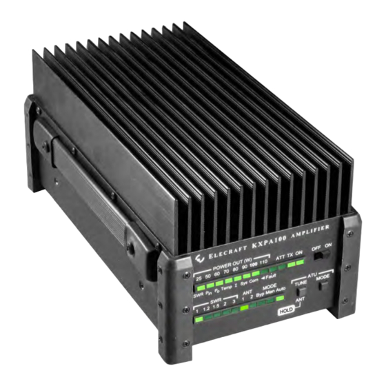
ELECRAFT KXPA100 Assembly Manual
100-watt amplifier
Hide thumbs
Also See for KXPA100:
- Owner's manual (55 pages) ,
- Manual (3 pages) ,
- Owner's manual (13 pages)
Table of Contents
Advertisement
Quick Links
Download this manual
See also:
Owner's Manual
Advertisement
Table of Contents

Related Manuals for ELECRAFT KXPA100


Summary of Contents for ELECRAFT KXPA100
- Page 1 KXPA100 LECRAFT 100-W MPLIFIER SSEMBLY ANUAL Revision A2, March 15, 2014 Copyright © 2014, Elecraft, Inc. All Rights Reserved...
-
Page 2: Table Of Contents
KXAT100 Antenna Tuning Unit ........................10 Connecting the Rear Panel Cables ........................15 Installing the Enclosure ............................. 18 Setup and Operation ..........................23 Appendix A Illustrated Parts List…..................... A1 Elecraft manuals with color images may be downloaded from www.elecraft.com. -
Page 3: Introduction
Every modern amplifier is complex, and the KXPA100 is no exception. All of the circuit boards have been fully tested and aligned. No test equipment is required. Only a few hand tools are needed to assemble your kit (see page Tools Required for Assembly on page 4). -
Page 4: Tools Required For Assembly
Who is covered: This warranty covers the original owner of the Elecraft product as disclosed to Elecraft at the time of order. Elecraft products transferred by the purchaser to a third party, either by sale, gift, or other method, who is not disclosed to Elecraft at the time of original order, are not covered by this warranty. -
Page 5: Preventing Electrostatic Discharge Damage
Preventing Electrostatic Discharge Damage Sensitive components may be damaged by Electrostatic Discharge (ESD) simply by touching them or a circuit board containing them unless you take specific steps to prevent such damage. Damage may occur with static discharges far too little for you to notice. A damaged component may not fail completely at first. -
Page 6: Unpacking And Inventory
A number of different types and sizes of screws and washers are used in the assembly. It is very important that you use the screw specified in each location or your finished KXPA100 may not fit together properly. In some places, using the wrong size screw may damage components. -
Page 7: Assembly Procedure
This can result in serious damage to your KXPA100 or, at a minimum, having to disassemble it to correct the mistake. Use your rule to check the length of screws and standoffs before installing them. Some components are only 1/16”... -
Page 8: Rear Panel Assembly
Rear Panel Assembly Locate the rear panel. The inside surface should be clean bare metal. It was taped to avoid overspray during painting. Remove any tape still present. If a large area is taped, you can break it away near one corner using a blunt tool that fits through a screw hole as shown in Figure 3 and then peel it off of the panel. - Page 9 This assembly consists of the heat sink with the KXPA100 PA Module attached and the KXPA100 LPF module mounted on it. With the heat sink sitting on your table, the LPF Module is the top pc board.
-
Page 10: Kxat100 Antenna Tuning Unit
KXAT100 Antenna Tuning Unit If you do not have the optional KXAT100 Antenna Tuning Unit, go directly to Connecting the Rear Panel Cables on page 15. There are four pan head screws securing the LPF Module to the standoffs below it. Remove each screw and lock washer and replace it with an M-F standoff as shown in Figure 6. - Page 11 Taking ESD precautions, remove the ATU module pc board from its packaging. Place it on the standoffs you just installed so that the two plugs on the ATU module mate with their corresponding sockets on the LPF module as shown in Figure 7. Be sure that both connectors are properly aligned so all of their pins engage. Figure 7.
- Page 12 Secure the ATU module pc board to the four standoffs using the screws and lock washers you removed earlier as shown in Figure 8. Note that there is a hole near the center of the ATU module that is not used. Figure 8.
- Page 13 The spacing between the ATU module and the low pass filter board below it is critical for the front panel to fit and the switches to operate smoothly. Before proceeding with the assembly, check to ensure the spacing is correct as follows: ...
- Page 14 Add the lock washer as shown below only if the front panel does not fit as shown in Figure 10. Figure 11. Adding Lock Washer to Standoffs. Remove the front panel and set it aside. It will be installed later.
-
Page 15: Connecting The Rear Panel Cables
Locate the envelope containing the SO-239 connector with a 4” (10.2 cm) cable attached packed with the ATU module and install it in the ANT 2 opening on the rear panel as shown in Figure 12. Figure 12. Mounting the ANT2 Connector on the Rear Panel. Connecting the Rear Panel Cables Locate the small connector attached by leads at one end of the amplifier. - Page 16 ANT2 opening as shown in the figure. CAUTION Failure to properly connect the cables may result in damage to your KXPA100. Be sure the TMP connectors are fully mated as shown in Figure 14. Figure 14. Mating TMP Connectors. Figure 15. Connecting the Rear Panel Cables with ATU Installed.
- Page 17 Figure 16. Connecting the Rear Panel Cables with no ATU. Pass the small jack through the hole marked RS232 (PC) on the rear panel and secure it with the hex nut (see Figure 17). Figure 17. Mounting the RS232 Jack in the Rear Panel.
-
Page 18: Installing The Enclosure
Installing the Enclosure Unwrap the U-Cover and inspect the flanges at both ends to ensure they are clean metal. Remove any paint overspray or masking tape that may have been left on them. If they are still taped, you can lift one corner of the tape and it will peel off in one piece. - Page 19 Place the U-Cover over the amplifier pc boards as shown in Figure 19. Be sure the lettering on the U-Cover is nearest to the rear panel with the SO239 connectors as shown, otherwise two of the bushings mounted in the side of the cover will strike the LPF module pc board.
- Page 20 Position the front panel so the LEDs, OFF/ON TUNE MODE switches fit through the openings. Secure the front panel with screws, lock washers and spacers just as you did on the rear panel (see Figure 21). The front panel for a KXAT100 with the optional ATU is shown. The alignment of the panel with the switches and LEDs requires more care when the ATU is installed.
- Page 21 Install a foot at each corner of the enclosure as shown in Figure 22. When the foot is pressed over the screws, lock washers and spacers you installed earlier and against the corner of the enclosure, the three remaining holes in the foot will line up with threaded bushings in the U-Cover to receive the additional three screws, lock washers and spacers.
- Page 22 Install the strap handle on the side of the KXPA100 as shown in Figure 23. Note that one side of the enclosure has two threaded bushings and the other side has four. Place the handle on the side with four bushings in the two closest to the heat sink.
-
Page 23: Setup And Operation
Setup and Operation That completes the assembly of your KXPA100. Refer to your KXPA100 Owner’s manual for Setup and Operation instructions. -
Page 24: Appendix A Illustrated Parts List
In addition to taking ESD precautions, be careful not to damage components on either side of the circuit boards when handling them. KXPA100-K RF Box E850586 ELECRAFT ILLUSTRATION DESCRIPTION QTY. PART NO. RF Assembly E870025 KXPA100-K Sheet Metal Box E850587 ELECRAFT ILLUSTRATION DESCRIPTION QTY. PART NO. U-Cover E850595 Rear Panel E850598... - Page 25 E700070 Washer, Flat, #6 E700067 Lock Washer, Split Ring, #4 E700010 Spacer, 1/8" (3.2 mm) long E700290 KXPA100 SO239 TMP Cable 2.5” Envelope E850589 ELECRAFT ILLUSTRATION DESCRIPTION QTY. PART NO. SO259 Connector with 2.5” (6.35 cm) cable and TMP connector E850599 SO259 –...
- Page 26 KXPA100 SO239 TMP Cable 4” Envelope E850584 ELECRAFT ILLUSTRATION DESCRIPTION QTY. PART NO. SO259 Connector with 4” (10.2 cm) cable and TMP connector E850600 SO259 – TMP Cable (typical) Screw, Pan Head, Black 4-40, E700294 5/16” (7.9 mm) Nut, 4-40 with captive star washer...
- Page 27 These parts are supplied only if you ordered the KXAT100 ATU option with your kit. ELECRAFT ILLUSTRATION DESCRIPTION QTY. PART NO. KXPA100 ATU PCB Assy E850572 KXPA100 Front Panel for ATU E850596 KXAT100 SO239 TMP Cable 4” Envelope E850584 ELECRAFT ILLUSTRATION DESCRIPTION QTY. PART NO.