ELECRAFT KXPA100 Owner's Manual
100-watt
Hide thumbs
Also See for KXPA100:
- Assembly manual (27 pages) ,
- Owner's manual (55 pages) ,
- Manual (3 pages)

Subscribe to Our Youtube Channel
Related Manuals for ELECRAFT KXPA100


Summary of Contents for ELECRAFT KXPA100
- Page 1 ® KXPA100 LECRAFT 100-W MPLIFIER ’ WNER ANUAL Draft, June 3, 2013 Copyright © 2013, Elecraft, Inc. All Rights Reserved...
-
Page 2: Table Of Contents
Contents Key to Symbols and Text Styles ....................... 3 Installation ..............................4 Operation ..............................6 Power On ..............................6 Band Switching ............................7 Transmitting ..............................7 Monitoring ..............................8 Fault Conditions ............................8 Firmware Updates ............................. 9 Specifications ............................10 Customer Service and Support ....................... -
Page 3: Key To Symbols And Text Styles
Key to Symbols Abbreviations and Text Styles Important – read carefully Operating tip T E M P Tap switch function (labeled above a switch) P K H O L D Hold switch function (labeled below a switch; hold for 1/2 sec. to activate) Light Emitting Diode... -
Page 4: Installation
The KXPA100 draws as much as 24 A of power supply current. The power cable should be as short and direct as possible to minimize voltage drop. The red power lead connects to positive (+) 13.8V and the black lead connects to the negative terminal. - Page 5 Connect the PA KEY {19} to the driving transmitter Key Output. This line must be grounded to transmit, and 1 mA of current is sourced. The KXPA100 PA KEY jack is pulled up to 5VDC when not transmitting. 5. Optional:...
-
Page 6: Operation
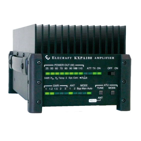
In the text, tap functions are shown like this: . An example of a hold function is T E M P P K H O L D Figure 2. KXPA100 Front Panel. NOTE: If at any time the LED {7} lights, refer to Fault Conditions, pg. 8. FAULT... -
Page 7: Band Switching
LEDs increases. Up to 5 watts of drive is required to produce the POWER (W) full 100 watts output from the KXPA100. If more than 5 watts is applied, enable the input attenuator (3 dB ATTEN) {17} by sliding its switch to the ON position. -
Page 8: Monitoring
Standing wave ratio (SWR) of the load and output power are displayed on LED bar graphs. Excessive levels may trigger a fault and either bypass the KXPA100 or shut the power off (see Fault Conditions below). Also two green LEDs indicate whether the amplifier is in standby (STBY) or operating (OPER) mode. -
Page 9: Firmware Updates
Please visit the Elecraft Software page (www.elecraft.com) to obtain our free firmware download application, KXPA100 Utility. Versions of the Utility program are provided for PCs, Macs, and Linux platforms. If you don’t have Internet access, you can obtain a firmware upgrade on CD. If you don't have a computer, you... -
Page 10: Specifications
Specifications All Amateur Bands from 1.8 to 29.7 MHz and 50 to 54 MHz Frequency Range 12-15V DC (13.8V Nominal), 24A (17A Nominal) Supply Voltage and Current Weight 4 lbs Size Enclosure only, 4.0 x 10.7 x 10.0 in., HWD (10.2 x 27.2 x 25.4 cm). With projections, 4.4 x 11.1 x 11.8 in. -
Page 11: Customer Service And Support
Elecraft products transferred by the purchaser to a third party, either by sale, gift, or other method, who is not disclosed to Elecraft at the time of original order, are not covered by this warranty. If the Elecraft product is being bought indirectly for a third party, the third party’s name and address must be provided at time of order to ensure... -
Page 12: Theory Of Operation
The output of the LPF bank is routed to the RF Output via the TR Switch. During receive or when the KXPA100 is in Standby (STBY), the TR switch routes the RF Input directly to the RF Output, bypassing both the PA Module and the Low Pass Filter Bank. - Page 13 KIT ASSEMBLY PROCEDURE...
Need help?
Do you have a question about the KXPA100 and is the answer not in the manual?
Questions and answers