ELECRAFT KPA500 Owner's Manual
500-watt
Hide thumbs
Also See for KPA500:
- Assembly instructions manual (54 pages) ,
- Owner's manual (28 pages) ,
- Manual (2 pages)
Table of Contents
Advertisement
Quick Links
Download this manual
See also:
Owner's Manual
Advertisement
Table of Contents

Related Manuals for ELECRAFT KPA500


Summary of Contents for ELECRAFT KPA500
- Page 1 ® KPA500 LECRAFT 500-W MPLIFIER ’ WNER ANUAL Draft, March 3, 2011 Copyright © 2011, Elecraft, Inc. All Rights Reserved...
-
Page 2: Table Of Contents
Contents Key to Symbols and Text Styles....................... 3 Installation ..............................4 Operation ..............................7 Power On ..............................7 Band Switching ............................8 Transmitting ..............................8 Monitoring ..............................9 Fault Conditions ............................10 Menu................................11 Firmware Updates........................... 12 Specifications............................13 Customer Service and Support ....................... 14 Theory of Operation .......................... -
Page 3: Key To Symbols And Text Styles
Key to Symbols Abbreviations and Text Styles Important – read carefully Operating tip T E M P Tap switch function (labeled above a switch) P K H O L D Hold switch function (labeled below a switch; hold for 1/2 sec. to activate) Light Emitting Diode Liquid Crystal Display... -
Page 4: Installation
Mains Voltage Settings CAUTION! Do not connect mains power to your KPA500 or attempt to turn it on before setting the fuse block switch and internal jumpers to match your supply voltage as described below; otherwise you may do extensive damage to your amplifier. - Page 5 Three taps are provided via red, green and yellow wires. Choose the tap according to the actual mains voltage at the outlet you plan to use for the KPA500. If you cannot measure your mains voltage, use the yellow tap.
- Page 6 {5} to the AUX connector on the AUX1 K3 using the optional cable. This cable is not required to operate your KPA500. It allows full use of the control functions on the K3. Note: This is not a common VGA computer cable.
-
Page 7: Operation
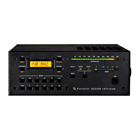
In the text, tap functions are shown like this: . An example of a hold function is T E M P P K H O L D Figure 2. KPA500 Front Panel. 3. Tap the . The LCD {4} and LED should light. -
Page 8: Band Switching
AUX cable is connected. Important: The automatic band selection function is active whenever PA KEY is low (in transmit mode) and overrides band selection made by any other means to protect the KPA500 from damage by wrong-band operation. -
Page 9: Monitoring
Excessive levels may trigger a fault and shut the KPA500 off (see Fault Conditions below). A red LED lights if a fault condition occurs. Also two green LEDs indicate whether the amplifier is in standby (STBY) or operating (OPER) mode. -
Page 10: Fault Conditions
High Level Faults If the indicator is on steady, one of the following high-level faults has occurred and the KPA500 has automatically switch to mode. Clear the fault, then tap the OPR/STBY switch to resume operation. -
Page 11: Menu
Menu Holding {3} enables the menu function to allow the following parameters to be set. With the menu M E N U function enabled, the MENU, EDIT and switches next to the symbols all respond to a simple tap. Use switches to scroll through the menu items. -
Page 12: Firmware Updates
Please visit the Elecraft K3 software page (www.elecraft.com) to obtain our free firmware download application, KPA500 Utility. Versions of the Utility program are provided for PCs, Macs, and Linux platforms. Some applications or peripheral devices may interfere with P3 downloads; check the Help information in KPA500 Utility if you have difficulty. -
Page 13: Specifications
Specifications All Amateur Bands from 1.8 to 29.7 MHz and 50 to 54 MHz Frequency Range 100 to 125 VAC or 200 to 250 VAC, 50/60 Hz, approx. 1000 VA Supply Voltage and Current Weight 26 lbs Size Enclosure only, 4.0 x 10.7 x 10.0 in., HWD (10.2 x 27.2 x 25.4 cm). With projections, 4.4 x 11.1 x 11.8 in. -
Page 14: Customer Service And Support
Elecraft products transferred by the purchaser to a third party, either by sale, gift, or other method, who is not disclosed to Elecraft at the time of original order, are not covered by this warranty. If the Elecraft product is being bought indirectly for a third party, the third party’s name and address must be provided at time of order to ensure... -
Page 15: Theory Of Operation
The output of the LPF bank is routed to the RF Output via the TR Switch. During receive or when the KPA500 is in Standby (STBY), the TR switch routes the RF Input directly to the RF Output, bypassing both the PA Module and the Low Pass Filter Bank. -
Page 16: Interface Cables
INTERFACE CABLES Aux Connector The KPA500 AUX connector has the following pin assignment. (PINOUT TABLE) AUX Interface Cable An optional interface cable is available for Elecraft K3 users. The pin assignments are as follows. (PINOUT TABLE) - Page 17 KIT ASSEMBLY PROCEDURE...
Need help?
Do you have a question about the KPA500 and is the answer not in the manual?
Questions and answers