ELECRAFT KPA1500 Owner's Manual
1500-watt amplifier
Hide thumbs
Also See for KPA1500:
- Owner's manual (36 pages) ,
- Application note (4 pages) ,
- Owner's manual (55 pages)
Table of Contents
Advertisement
Quick Links
Download this manual
See also:
Owner's Manual
Advertisement
Table of Contents

Subscribe to Our Youtube Channel
Related Manuals for ELECRAFT KPA1500


Summary of Contents for ELECRAFT KPA1500
- Page 1 KPA1500 LECRAFT 1500-W MPLIFIER ’ WNER ANUAL Revision B, May 16, 2018 E740301 Copyright © 2018, Elecraft, Inc. All Rights Reserved...
-
Page 2: Introduction
TR is completely noise-free thanks to the use of PIN-diode switching. The KPA1500 comes with a built-in Automatic Antenna Tuner (ATU) that can handle a load SWR up to 3:1 at the full 1500 watt output in any mode. -
Page 3: Table Of Contents
FCC-Mandated Part 15 Notice for the Computer Interface Ports ............6 In the Box ..............................6 Installation ..............................7 Positioning the KPA1500 RF Deck and Power Supply ..................9 Cabling – Power Supply ............................9 Cabling – RF Deck .............................. 9 Operation .............................. - Page 4 CW Key Tune Cable ............................41 Yaesu Transceivers ............................42 BCD Interface ..............................43 Kenwood Transceivers ............................43 Flex Transceivers .............................. 43 In Case of Difficulty ..........................44 Appendix A—KPA1500 Tuner Frequency Segments ................45 Elecraft manuals with color images may be downloaded from www.elecraft.com.
-
Page 5: Power Supply
Before opening the KPA1500 RF Deck or Power Supply enclosures: 1. Turn off the KPA1500 by tapping the front panel ON switch and wait until the fan stops. (The fan drains the power supply to a safe voltage.) 2. -
Page 6: Fcc-Mandated Part 15 Notice For The Computer Interface Ports
Connect the equipment to an outlet on a different circuit from that to which the receiver is connected. • Consult the dealer or an experienced radio/TV technician for help. Regarding the computer interface: changes or modifications not expressly approved by Elecraft could void the user’s authority to operate the equipment. Elecraft Inc. -
Page 7: Installation
Control circuit connection to the KPA1500 power supply. Accepts a 12V input signal for remote control applications to command the KPA1500 to turn on or off. Can also be connected to K3/K3S rear panel 12V DC OUT RCA connector so the KPA1500 turns on when the transceiver turns on. - Page 8 The KPA1500 Power Supply Deck rear panel is shown below. The connectors and controls are described below the figure. Figure 2. KPA1500 Power Supply Deck Rear Panel. Control: DA-15 cable with control and low voltage supplies to the RF Deck.
-
Page 9: Positioning The Kpa1500 Rf Deck And Power Supply
Supply can be operated remotely so there is no need for it to be within the operator’s reach. The fans operate whenever the KPA1500 is on, so you can place the Power Supply under the operating desk or elsewhere to minimize fan noise. - Page 10 The optional KPAK3AUX cable kit provides closer integration with a K3 or K3 by sharing band information between the KPA1500 and the transceiver, see Figure 5, page 12 and Figure 6, page 13. The KPAK3AUX cable kit enables all enhanced features described under Operation, including coordinated band-switching (page 15).
- Page 11 KPA1500 HF to 6 m Transceiver Figure 4. Basic Cabling Diagram for Any Transceiver.
- Page 12 KPA1500 Figure 5. K3 Enhanced Cabling Using KPAK3AUX Cable, Without Interrupter.
- Page 13 KPA1500 Figure 6. K3 Enhanced Cabling Using KPAK3AUX Cable and Separate Key Line, With Interrupter.
-
Page 14: Operation
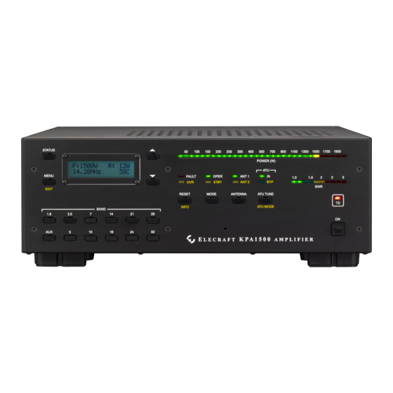
Operation RF Deck Front Panel Controls Figure 7. KPA1500 RF Deck Front Panel Controls and Indicators. The front panel controls and indicators are referred to in the following operating instructions by the numbers shown in Figure 7. Below is a summary of the function of each control and indicator. -
Page 15: Power On
AC mains power is applied to the Power Supply. Keeping the control circuitry energized allows the KPA1500 to be turned on and off remotely as well as from the front-panel switch. If you do not need to control the KPA1500 remotely and would prefer to save the small amount of power required to power the control circuitry, either switch the Power Supply completely off or provide an external mains power switch capable of handling 20A. -
Page 16: Antenna Selection
By default, the KPA1500 will return to that ANT1 ANT2 choice when returning to that band. You can configure this function with the KPA1500 Utility Configuration panel. You can also disable one of the antenna outputs for selected bands. See... -
Page 17: Using Automatic Level Control (Alc)
If you use the AUX cable interface between the K3 or K3 and KPA1500 (Figure 5, page 12 or Figure 6, page 13), and you have RADIO TYPE set to K3 or K3s, the KPA1500 will send the operate/standby status to the K3 or K3... -
Page 18: Automatic Antenna Tuner (Atu)
Automatic Antenna Tuner (ATU) The internal ATU may be used with the KPA1500 in either standby or operate mode. When the KPA1500 is in standby mode, power from the driving transceiver is passed directly to the ATU. Press and hold... - Page 19 If the SWR is 1.2 or less when a tune operation begins, the KPA1500 bypasses the matching network without searching for a tuning solution. The and the LEDs both illuminate to show the tuner is ATU IN ATU BYP bypassed for this frequency. When returning to the selected frequency, the internal ATU will recall the bypass mode.
- Page 20 With ATU HiSWR AUTO RETUNE set to ENABLED and an antenna SWR higher than the retune threshold, the KPA1500 will search previous tuner settings until one is found that is as good as or better than the SWR threshold. Once found, the setting is stored and the amplifier quickly resumes operation.
-
Page 21: Amplifier Monitoring And Status Indicators
LED in the bargraph varies as power increases through its range. The bargraphs are color-coded: green for normal, yellow for marginal and red for excessive levels. Excessive levels may trigger a fault and switch the KPA1500 to (see Fault Conditions, page 24). The... - Page 22 E L EC RA FT Text appears briefly on the LCD when the amplifier is switched on. You may Banner customize this text with the KPA1500 K P A1 5 00 Utility Edit Configuration dialog. Forward Power, F: 9 83W 5 6 %...
-
Page 23: Remote Operation
Button has no operation programmed. Remote Operation The KPA1500 can be controlled remotely using a personal computer connected to the RJ45 Ethernet port or to the USB port. A basic remote operating capability is built into the KPA1500 Utility program OPERATE tab, see page 29. -
Page 24: Fault Conditions
O P ER / ST B Y switch to LCD. return the KPA1500 to normal operation, or tap the R E S ET switch to return the KPA1500 to standby mode. Hard Faults require the operator to correct the condition and reset the amplifier. - Page 25 BAND switch while editing the menu item to view and change the configuration for each band. Optionally, you may use the KPA1500 Utility program (page 29) to modify several settings on all bands at once. • Some menu items, such as serial number and firmware revision, may not be edited.
- Page 26 When the ALARM TONE menu item is changed from OFF to ON, a sample fault alarm tone is sounded. KPA1500 provides an ALC voltage between 0 and -12V, a function of output power and this per-band ALC THRESH value. If ALC is used at all,...
- Page 27 The KPA1500 sends another message to stop tuning. ATU XCVR KEY When ATU XCVR KEY is ON, the KPA1500 asks the K3 for TUNE (Tech Mode Only) POWER when it performs an ATU HiSWR RETUNE tune or a full search tune (press of the KPA1500 ATU TUNE switch).
- Page 28 Select when a K3 or K3 is connected through a 15-pin AUX cable to your KPA1500, which appears to a K3 as a combination of KPA500 and KAT500. BCD: The 4 BAND lines on the ACC connector carry band information in a BCD format.
-
Page 29: Kpa1500 Utility Program
KPA1500 firmware and may be used to more quickly edit various parameter settings. 1. Download the KPA1500 Utility program and install it on your computer. 2. Connect the USB A to B interface cable supplied with your KPA1500 between the USB port on the KPA1500 rear panel and your personal computer. -
Page 30: Wattmeter Calibration Procedure
6. Transmit briefly at 1500 W output into the external wattmeter and dummy load and compare the reading on the external wattmeter with the KPA1500 wattmeter. 7. If you wish to adjust the power displayed on the KPA1500 LCD and LEDs, hold M EN U... -
Page 31: Specifications
Specifications The following performance specifications are guaranteed only within the Amateur bands. Frequency Range All Amateur bands from 1.8 to 29.7 MHz and 50 to 54 MHz Supply Voltage and 195 to 250 VAC, 50/60 Hz up to 20A Current RF Deck Weight 22 lbs. - Page 32 3 — 30 MHz 1500 W into 16 Ω to 150 Ω (3:1 SWR) Antenna Tuning Unit Matching 750 W into 5 Ω to 500 Ω (10:1 SWR) Range and Power Limits 1.8 — 2 MHz 1500 W into 16 Ω to 150 Ω (3:1 SWR) 750 W into 12 Ω...
-
Page 33: Customer Service And Support
Elecraft products transferred by the purchaser to a third party, either by sale, gift, or other method, who is not disclosed to Elecraft at the time of original order, are not covered by this warranty. If the Elecraft product is being bought indirectly for a third party, the third party’s name and address must be provided at time of order to ensure... -
Page 34: Theory Of Operation
Figure 9. KPA1500 Block Diagram. Switching When the KPA1500 is in operate mode, the transmit-receive (TR) switch routes RF from the driving transceiver to the power amplifier (PA) module where it is amplified by a pair of LDMOS (Laterally Diffused metal oxide semiconductor) transistors. - Page 35 RF output, reflected power (high SWR) or current is drawn by the finals. • If an unauthorized frequency is transmitted, the KPA1500 switches to standby until RF drive is removed. This fault will automatically reset if a valid frequency is applied. •...
- Page 36 The Tuning Segments Since retuning is normally required over a narrower frequency range on the lower frequencies to maintain a low SWR, the lower frequencies have narrower segments assigned as follows: • Below 3 MHz the segments are 10 kHz wide. •...
-
Page 37: Aux And Xcvr Serial Connector Interfaces
AUX p ort, described above and the port. XCVR SERIAL port provides RS232 level data for other transceivers such as the Elecraft K2 and some XCVR Serial Kenwood, Yaesu and Icom transceivers. Below are the signals available at the connector. -
Page 38: Elecraft Kpak3Aux Interface Cable
Various models of Icom radios use either a 13-pin DIN or an 8-pin DIN connector. Be sure to use the connector that is correct for your radio. Pins not shown have no connection. Check with Elecraft Customer Support or (www.elecraft.com) for radios that are directly supported with an Elecraft cable. -
Page 39: Xcvr Serial Cable
If the band reference voltage is far from 8V, band voltage is ignored. This band voltage scheme does not provide unique voltages for each band. KPA1500 chooses 7, 21 and 28 MHz when there is ambiguity. For this reason (and ATU recall by frequency segment within a band), a CI-V connection is preferable for Icom frequency information. -
Page 40: Tune Cable
When the KPA1500 is configured for ICOM Mode, it operates as a 2-terminal CI-V compatible port that works with Icom and some TenTec transceivers: Tip = Data, Ring = No connection and Sleeve = Ground. When configured in SERIAL mode, it is a TTL-level serial port:... -
Page 41: Cw Key Tune Cable
TUNE rear panel. With this connection, the KPA1500 provides a “AH4 KEY” logic level to cause the Icom transceiver to generate steady RF carrier for ATU tuning. When tuning completes, the KPA1500 removes the “AH4 KEY” level to un- key the Icom transceiver, putting the KPA1500 in standby Mode. -
Page 42: Yaesu Transceivers
Although various models of Yaesu radios use either DIN8/262 or a MiniDIN8 connector, the pin connections are the same. Pins not shown have no connection. See the table below. Check with Elecraft Customer Support (support@elecraft.com) for radios that are directly supported with an optional Elecraft cable. -
Page 43: Bcd Interface
VFO information can be interfaced via the KPA1500 interface. XCVR SERIAL jack and a 3.5mm TRS plug for the KPA1500 side. Set the KPA1500 RADIO menu item Use the XCVR SERIAL to SERIAL Mode. Tip = TX DATA, Ring = RX DATA and Sleeve = Ground. See Figure 10, page 40. -
Page 44: In Case Of Difficulty
Review text displayed in the LCD for specific fault and take FAULT LED appropriate action. Bring up the KPA1500 Utility to inspect the Fault Log. This will provide details on what the KPA1500 saw when it determined the Fault condition. -
Page 45: Appendix A-Kpa1500 Tuner Frequency Segments
Appendix A—KPA1500 Tuner Frequency Segments KPA1500 Amateur Band ATU Segment Center Frequencies Frequencies in MHz 10 kHz 1.805 1.815 1.825 1.835 1.845 1.855 1.865 1.875 1.885 1.895 Segments 1.905 1.915 1.925 1.935 1.945 1.955 1.965 1.975 1.985 1.995 20 kHz 3.510... - Page 46 KPA1500 ATU Segment Center Frequencies–All Segments Center Frequencies in MHz Amateur Band Frequencies Shown in 10kHz 1.505 1.515 1.525 1.535 1.545 1.555 1.565 1.575 1.585 1.595 Segments 1.605 1.615 1.625 1.635 1.645 1.655 1.665 1.675 1.685 1.695 1.705 1.715 1.725 1.735...
- Page 47 Center Frequencies in MHz Amateur Band Frequencies Shown in 8.410 8.430 8.450 8.470 8.490 8.510 8.530 8.550 8.570 8.590 8.610 8.630 8.650 8.670 8.690 8.710 8.730 8.750 8.770 8.790 8.810 8.830 8.850 8.870 8.890 8.910 8.930 8.950 8.970 8.990 9.010 9.030 9.050 9.070...
- Page 48 Center Frequencies in MHz Amateur Band Frequencies Shown in 18.210 18.230 18.250 18.270 18.290 18.310 18.330 18.350 18.370 18.390 18.410 18.430 18.450 18.470 18.490 18.510 18.530 18.550 18.570 18.590 18.610 18.630 18.650 18.670 18.690 18.710 18.730 18.750 18.770 18.790 18.810 18.830 18.850 18.870...
- Page 49 Center Frequencies in MHz Amateur Band Frequencies Shown in 50.100 50.300 50.500 50.700 50.900 51.100 51.300 51.500 51.700 51.900 52.100 52.300 52.500 52.700 52.900 53.100 53.300 53.500 53.700 53.900 54.100 54.300 54.500 54.700 54.900 55.100 55.300 55.500 55.700 55.900 56.100 56.300 56.500 56.700...
Need help?
Do you have a question about the KPA1500 and is the answer not in the manual?
Questions and answers