Table of Contents
Advertisement
Quick Links
Advertisement
Table of Contents

Related Manuals for Baumatic BH97BS


Summary of Contents for Baumatic BH97BS
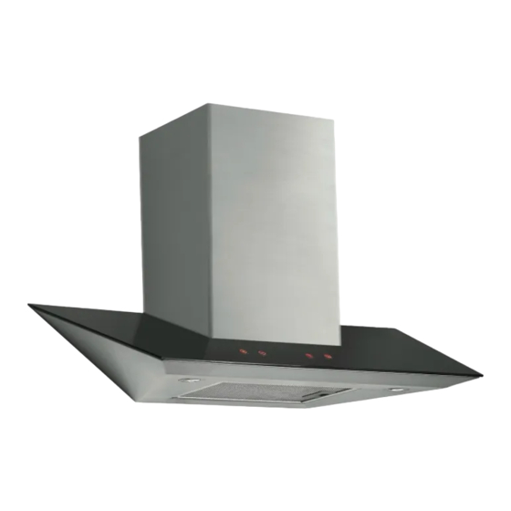
- Page 1 BH97BS 90 cm Glass Chimney Hood...
- Page 3 User Manual for your Baumatic BH97BS 90 cm Glass Cooker Hood NOTE : This User Instruction Manual contains important information, including safety & installation points, which will enable you to get the most out of your appliance. Please keep it in a safe place so that it is easily available for future reference;...
-
Page 4: Table Of Contents
IMPORTANT SAFETY INFORMATION 6 – 8 Specifications of your cooker hood Product dimensions Specifications Using your Baumatic cooker hood 10 - 11 The control panel Switching the cooker hood on and setting the fan speed 10 - 11 The cut off timer... -
Page 5: Environmental Note
ENVIRONMENTAL NOTE Note: Before discarding an old appliance, switch off and disconnect it from the power supply. Cut off and render any plug useless. Cut the cable off directly behind the appliance to prevent misuse. This should be undertaken by a competent person. -
Page 6: Important Safety Information
IMPORTANT SAFETY INFORMATION Your safety is of the utmost importance to Baumatic. Please make sure that you read this instruction booklet before attempting to install or use the appliance. If you are unsure of any of the information contained in this booklet, please contact the Retailer where you purchased your unit from. - Page 7 o When installed between adjoining wall cabinets, the cabinets must not overhang the hob. o The edges of the cooker hood are sharp – be mindful of this as you handle your appliance, especially during installation and cleaning. DO NOT CLEAN IN BEHIND THE GREASE FILTERS! o If the room where the cooker hood is to be used contains a fuel burning appliance such as a central heating boiler then its flue must be of the sealed or balanced flue type.
- Page 8 o The manufacturer refuses to accept any responsibility for damages arising to the hood or it catching on fire, from a failure to observe the fire safety advice contained in this instruction booklet. o Remember that when in extraction mode, your cooker hood is removing air from your room.
-
Page 9: Specifications Of Your Cooker Hood
Specifications of your cooker hood PRODUCT DIMENSIONS Height: 595 - 1075 mm Width: 900 mm Depth: 500 mm DIMENSIONS OF CHIMNEY SECTION: Width: 375 mm Depth: 271 mm Your cooker hood is fitted with: o Touch control operation o 3 Speeds o 1 x Washable aluminium grease filter o 2 x LED lights o Extraction capacity: 750 m³/hr... -
Page 10: Using Your Baumatic Cooker Hood
Using your Baumatic cooker hood The control panel o Make sure that it has been installed by a suitably qualified person, information contained Baumatic’s installation instructions. o Find the control panel, which is located in the middle of the canopy. -
Page 11: The Cut Off Timer
YOUR HOOD TEN MINUTES BEFORE YOU START TO COOK, OR AT THE VERY LEAST WHEN YOU BEGIN COOKING. YOU SHOULD ALSO RUN YOUR HOOD FOR TEN MINUTES AFTER YOU HAVE FINISHED COOKING. Cleaning your Baumatic cooker hood IMPORTANT: BEFORE CLEANING,... -
Page 12: The Grease Filter
o Never attempt to clean the area above the grease filter. o IMPORTANT: You should regularly use a good quality stainless steel cleaner to maintain the shine and finish on the stainless steel areas of your cooker hood. o This will help to leave a silicone water-resistant film to protect the stainless steel surfaces and keep them in good condition for the life of the product. - Page 13 o First remove the grease filter by pulling down on the handle and pulling them away from cooker hood. o Soak the grease filter in hot water and washing up liquid for at least 3 minutes. Then use a soft brush to loosen any grease deposits that have formed.
-
Page 14: Changing A Light Bulb
Changing a light bulb IMPORTANT: BEFORE ATTEMPTING TO CHANGE A LIGHT BULB, YOU MUST ENSURE THAT YOU HAVE DISCONNECTED THE COOKER HOOD FROM YOUR MAINS SUPPLY. o Prior to touching the light bulbs ensure they are cooled down. o First remove the grease filter by pulling down on the handle and pulling it away from the cooker hood. -
Page 15: Fitting The Carbon Filter
o Fit the replacement bulbs, bulb holders and wiring in the same manner as the originals. o Reconnect the light wiring point. o IMPORTANT: Defective bulbs should be replaced immediately. o If the light or lights still do not work, make sure that the lamps are fitted properly into their housings before you call for technical assistance. -
Page 16: Installation
2) Hook the carbon filter over the pins that are located at the end of the motor. 3) Turn the carbon filter anticlockwise, until you feel it click into place. o Repeat this process for the second carbon filter. You need to place a carbon filter at either end of the motor. -
Page 17: Electrical Connection
Electrical connection YOUR COOKER HOOD IS INTENDED FOR FITTED AND PERMANENT INSTALLATION. o The cooker hood’s power cable must be fitted upstream from the electrical connection, using an omni-polar switch with a contact distance of at least 3 mm. THE FUSE MUST BE RATED AT 3 AMPS. -
Page 18: Extraction Mode Or Recirculation Mode
o Ensure that all electrical connections are carried out by a suitably qualified person. o Before commencing installation of the cooker hood the grease filter should be removed. o Check inside the product and insure that there is no transit packaging or any other materials, such as packets of screws, guarantees etc. -
Page 19: Installing Your Cooker Hood
In recirculation mode stale air is taken via the grease filter, and passed through a charcoal filter for purification. The air then re-enters the kitchen via an opening in the hood For optimum performance, we recommend that the cooker hood is used in extraction mode and connected to external ducting. - Page 20 2) Position the hood against the wall that you are intending to install it on and mark the position of the screw holes that are to be drilled (as shown in the figure below). 2a) The support screw holes are indicated by figure A in this drawing and the anchoring screw holes are indicated by figure B.
- Page 21 3) Using a drill bit with an 8 mm diameter, make holes in the wall on the positions that you have marked in step 2. 4) Insert rawl plugs into all of the holes that you have drilled. 5) Fasten the support screws halfway in, leaving them 10 mm out of the wall.
-
Page 22: Connecting To External Ducting
7) Fully tighten the support screws (A) and then screw the anchoring screws (B) through the relevant holes in the cooker hood. Fully tighten the anchoring screws into the wall. Connecting to external ducting 8) Connect the coupling to the top of the cooker hood, and then connect a 125 mm ducting hose to the coupling (please note that the ducting hose is not supplied with the appliance). - Page 23 o Mark the side measurement of both sides of chimney section (C) on the wall with a pencil. 10) Lift chimney section (D) upwards until it reaches the ceiling. You must ensure that it is perpendicular to the hood. o Mark the side measurements of both sides of chimney section (D) on the wall with a pencil and then remove chimney section (D).
- Page 24 11) Take the flat bracket (E) and place it between the two pencil marks that you made in step 9 o Keeping the bracket in contact with the wall, use a pencil to mark on the wall the anchoring holes that are cut out of the bracket.
-
Page 25: Completing The Installation
13) Lift chimney section (D) up to the ceiling and secure it to the L shaped bracket using the screws provided. Completing the installation o If you are setting the appliance to recirculation mode, then you should now fit the two carbon filters. See the “Fitting the carbon filters”... - Page 26 o If the hood is set up for recirculation mode, check that the carbon filters do not need replacing. o If the hood is set up for extraction mode, check that the ducting hose and discharge outlet are not blocked. My cooker hood has switched off during operation.
- Page 27 Or any installation other than the one specified by Baumatic Ltd. has been completed. Please refer to the conditions of guarantee that appear on the warranty card that you receive with the appliance.
-
Page 28: Contact Details
Service Telephone 1800 444 357 Website www.thinkappliances.com Applico Ltd. P.O. 92900 Onehunga, Auckland, New Zealand 1061 Website www.applico.nz United Kingdom Baumatic Ltd., Baumatic Buildings, 6 Bennet Road, Reading, Berkshire RG2 0QX United Kingdom Sales Telephone (0118) 933 6900 Website: www.baumatic.co.uk...
Need help?
Do you have a question about the BH97BS and is the answer not in the manual?
Questions and answers