Table of Contents
Advertisement
Operation/Repair/Parts
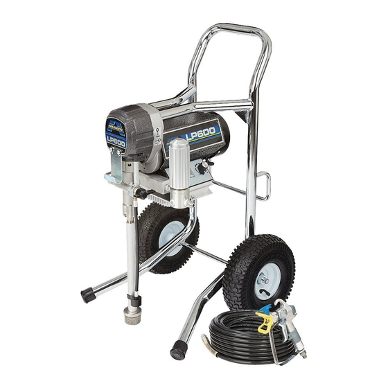
Airless Paint Sprayer
For application of architectural paints and coatings.
Airlessco LP500, LP600, Allpro Mustang 5100 - 8100
3000 psi (20.7 MPa, 207 bar) Maximum Working Pressure
Important Safety Instructions
Read all warnings and instructions in this
manual. Save these instructions.
Related Manuals
Gun Manual
312363 - English
312364 - Spanish
312365 - French
24F568 LP500 HiBoy
24F571 LP600 HiBoy
24F581 Mustang 5100 Hi Boy
24F583 Mustang 8100 HiBoy
24F569 LP500 LoBoy
24F570 LP600 LoBoy
3A1185B
24F567 LP500 Stand
24F579 Mustang 5100 Stand
ti16111a
ti16112a
ENG
ti16113a
Advertisement
Table of Contents

Subscribe to Our Youtube Channel
Related Manuals for AIRLESSCO 24F568 LP500 HiBoy


Summary of Contents for AIRLESSCO 24F568 LP500 HiBoy
- Page 1 Operation/Repair/Parts 3A1185B Airless Paint Sprayer For application of architectural paints and coatings. Airlessco LP500, LP600, Allpro Mustang 5100 - 8100 3000 psi (20.7 MPa, 207 bar) Maximum Working Pressure 24F568 LP500 HiBoy Important Safety Instructions 24F571 LP600 HiBoy Read all warnings and instructions in this...
- Page 2 Warnings Warnings The following warnings are for the setup, use, grounding, maintenance, and repair of this equipment. The exclama- tion point symbol alerts you to a general warning and the hazard symbols refer to procedure-specific risks. When these symbols appear in the body of this manual, refer back to these Warnings. Product-specific hazard symbols and warnings not covered in this section may appear throughout the body of this manual where applicable.
- Page 3 All parts of the spray system, including the pump, hose assembly, spray gun, and objects in and around the spray area shall be properly grounded to protect against static discharge and sparks. Use Airlessco conductive or grounded high-pressure airless paint sprayer hoses.
- Page 4 • Do not kink or over-bend the hose. • Do not expose the hose to temperatures or to pressures in excess of those specified by Airlessco. • Do not use the hose as a strength member to pull or lift the equipment.
- Page 5 Warnings WARNING WARNING WARNING WARNING MOVING PARTS HAZARD Moving parts can pinch, cut or amputate fingers and other body parts. • Keep clear of moving parts. • Do not operate equipment with protective guards or covers removed. • Pressurized equipment can start without warning. Before checking, moving, or servicing equipment, follow the Pressure Relief Procedure, page 7 and disconnect all power sources.
-
Page 6: Component Identification
Component Identification Component Identification ti14791a ti14790a ti16050a Power switch Turns sprayer ON and OFF Fuse Pressure Control Knob Adjusts pressure. Turn clockwise to increase pressure and counterclockwise to decrease pressure. Prime/Pressure (PR) Relief Valve Primes pump and relieves pressure from gun, hose and tip. Prime/Pressure (PR) Relief Valve Open Relieves pressure from gun, hose and tip and primes the unit Position... -
Page 7: Operation
Operation Operation Pressure Relief Procedure 5. Re-engage gun trigger lock and close Prime/Pres- sure Relief Valve.Turn Prime/Pressure Relief Valve (PR Valve) to the open (priming) position to relieve residual pressure. To reduce risk of injury, follow this pressure relief pro- cedure whenever you see this symbol throughout this manual, Also, perform this procedure whenever you: •... -
Page 8: Prime And Flush Storage Fluid
Operation Fill the Packing Nut/Wet Cup Flushing 1. Remove guard and cap. 2. Fill the Packing Nut/Wet Cup with 5 drops of Air- lessco Throat Seal Oil (TSO). • To reduce the risk of static sparking, which can cause fire or explosion, always hold a metal part of the gun firmly against the metal pail when flushing. -
Page 9: Adjusting The Pressure
Operation 6. Turn the engine ON/OFF switch to ON. Prime/PR Valve must be “OPEN” in the prim- ing position. 7. Point the gun into the metal pail and hold a metal After ensuring the gun trigger lock is engaged, part of the gun firmly against the pail. Maintain firm attach tip and safety guard. -
Page 10: Short Term
Operation Shutdown Storage 1. Relieve Pressure, page 7. Short Term 2. Clean the tip and gun as recommended in the sepa- 1. Flush sprayer with compatible solvent before stor- rate Gun Manual supplied with the gun. ing, then fill the pump and hoses with an oil based solvent such as mineral spirits. -
Page 11: Daily Maintenance
1. Keep the displacement pump packing nut/wet cup Pump Conditioner and water, a 50’ 1/4” airless hose, air- lubricated with Airlessco TSO (Throat Seal Oil) at all less gun and tip on unit, open the prime valve and switch times. The TSO helps protect the rod and packings. -
Page 12: Servicing The Outlet Valve
7. Tighten packing nut clockwise until resistance is felt (4). against the Belleville Springs, go 3/4 of a turn more. Put five drops of Airlessco Throat Seal Oil in the 5. Inspect outlet ball (4) and seat for wear. Replace as packing nut. -
Page 13: Servicing The Inlet Valve
Before reinstalling the outlet seat (6) support, apply two drops of Loctite No. 242 (blue) on the threads and torque to 20 ft-lbs. NOTE: Airlessco LP pump tool kit is required for this task. Kit includes: Tightening Bar (865008), Packing Removal Tool (331465), Piston Holder (331195), 3/8”... - Page 14 Maintenance Reassembly of the Fluid Pump 13. Take the packing holder (20) and replace the white O-ring (24) and the black O-ring (25) with new ones 1. Place lower male gland(1) down on the flat side. from the packing kit. 2.
-
Page 15: Gear And Pump Assembly
Maintenance Gear and Pump Assembly Pressure Control Assembly Calibration Servicing Gear box Assembly NOTE: Anytime a sensor or pressure control assembly 1. Remove fluid pump. See Fluid Pump Disconnect, (board) or both are replaced, the following calibrations page 11. must be performed. 2. -
Page 16: Replacement Of Electrical Components
Maintenance Pressure Calibration 2. Place the suction tube into a bucket of Pump Condi- tioner. 1. Complete the ZERO calibration, as per “ZERO CAL- IBRATION” prior to commencing this calibration. 3. Turn pump on and turn up pressure control until the machine starts to prime. -
Page 17: Fuse Holder
Maintenance Sensor Fuse Holder 1. Remove the four screws, heatsink, and lower the 1. Lower pressure control assembly as described pressure control assembly. above. 2. Disconnect swivel from sensor by holding sensor 2. Disconnect the two wires on the toggle switch. with 7/8”... -
Page 18: Troubleshooting
Troubleshooting Troubleshooting Problem Cause Solution Unit doesn’t prime Airleak due to loose suction nut Tighten suction nut. Airleak due to worn o-rings Replace o-ring (110636) on suction seat and o-ring (867390) below suction seat. Airleak due to hole in suction Replace suction hose. - Page 19 Troubleshooting Problem Cause Solution Power Source Using a Phillips Head screwdriver, remove the four screws holding the pressure control assembly. Locate the red light on the board indicating there is power (it will be red). If the light is ON, see Pressure Control Assembly (Board).
- Page 20 Troubleshooting Problem Cause Solution Sensor Plug another sensor board into the board and perform the zero calibration procedure. If the machine starts to run, the sensor is bad. If there is no replacement sensor available, use a multi-meter to test the resistance across the red and black wires of the sensor (be sure to test the plug).
-
Page 21: Optional Manifold Filter
Parts Parts Optional Manifold Filter (865627) ti16052a Ref. Part Description Qty. Ref. Part Description Qty. 867145 Cover, filter 867077 Base, filter 301356 Spring 867004 Swivel 867377 O-Ring 867420 Plug 3/8” 867214 Filter 60 Mesh 867309 Nipple 3/8”M x 1/4”M 867647 Support 867417 Plug 1/4”... -
Page 22: Fluid Pump
Parts Fluid Pump Ref. Part Description Qty. 866082 Connecting Rod pin 331117 Sleeve 331062 Retaining Ring 867783 Plug 162453 Hose Connector 867005 Swivel 331034 Suction Nut 867539 Bolts 331236 Fluid Pump (Hi-Boy) 331209 Fluid Pump (Lo-Boy) 331093 Piston Rod 331074 Tube Spacers 331111 Connection Rod Shield 331038 Connecting Rod 5, 6... -
Page 23: Inlet Valve
Parts Inlet Valve Ref. Part Description Qty. 331011 Fluid Pump Body 331029 Suction Ball Guide 331030 Suction Ball 108526 O-Ring 331409 Suction Seat (Lo-Boy) 331292 Suction Seat (Hi-Boy) 331034 Suction Nut ti16115a Outlet Valve Ref. Part Description Qty. 331330 Piston 331195 Piston Holder 331196 Dowel Pin 331027 Outlet Ball... -
Page 24: Packing Replacement
Parts Packing Replacement ti16057a Ref. Part Description Qty. Ref. Part Description Qty. 331014 Male Gland 331025 Belleville Springs 331016 Packing Polyethylene 331022 Male Gland 331308 Female Adaptor 331023 Packing Polyethylene 331011 Fluid Pump Body 331021 Female Gland 331029 Suction Ball Guide 331019 Packing Holder 331030 Suction Ball 331037 Packing Nut... - Page 25 Parts Ref. Part Description Qty. 331014 Male Gland 331016 Packing Polyethylene 331308 Female Adaptor 331011 Fluid Pump Body 331029 Suction Ball Guide 331030 Suction Ball 108526 O-Ring 331409 Suction Seat (Carry and Lo-Boy) 331292 Suction Seat (Hi-Boy) 331034 Suction Nut 331026 Outlet Seat Retainer 331026 Outlet Seat 111457 O-Ring...
- Page 26 Parts Gear and Pump Assembly Motor ti16058a Ref. Part Description Qty. Ref. Part Description Qty. 107445 Bolt 11 331074 Tube Spacer 866338 Shoulder Bolt 12 331111 Shield 331117 Sleeve 13 331234 Cover 331062 Retaining Spring 14 331046 Bearing 331209 Pump Assembly (Carry and Lo-Boy) 15 331038 Crosshead Assembly 331236 Pump Assembly (Hi-Boy)
-
Page 27: Stand Frame Models
Parts Stand Frame Models 1, 2 ti16114a Ref. Part Description Qty. Ref. Part Description Qty. 331785 Fan 331111 Shield 331786 Fan Cover 331234 Cover 867291 Knob 331401 Frame Assembly 331321 Terminal Box 119048 Screw 331787 Bolt (.6HP) HSE1450 Hose 1/4” x 50’ (not shown) 867505 Heatsink Screw Gun, Spray (not shown) 867557 Screw... -
Page 28: Lo-Boy Models
Parts Lo-Boy Models 14 13 ti16117a Ref. Part Description Qty. Ref. Part Description Qty. 331785 Fan 331174 Handle 331786 Fan Cover 867488 Screw 331476 Cup, Suction Drain 331176 Bushing 143029 Collar 331365 Frame Assembly 867736 10” Wheel 119048 Screw 305039 Spacer 331788 Bolt (.9HP) 867291 Knob... -
Page 29: Hi-Boy Models
Parts Hi-Boy Models 11, 12, 13 ti16060a Ref. Part Description Qty. Ref. Part Description Qty. 331795 Motor Cover 119048 Screw 331788 Bolt (.9HP) 331785 867281 Knob 331786 Fan Cover 331321 Terminal Box HSE1450 Hose, 1/4” x 50’ (not shown) 867505 Heatsink Screws Gun, spray (not shown) 143029... -
Page 30: Suction Assemblies
Parts Suction Assemblies Carry Chassis (865717) Hi-Boy Chassis (331284) ti16061a Ref. Part Description Qty. 301348 Bypass Hose Assembly 331034 Suction Nut 331292 Suction Seat Assembly 331400 Inlet Tube ti16062a 187190 Inlet Strainer Ref. Part Description Qty. 331290 Suction Hose Assembly 187651 Inlet Strainer Prime Valve 867370 PTFE O-Ring... -
Page 31: Electrical System
Parts Electrical System BLACK GREEN & & A2 A1 INHIBIT SWITCH S1 S2 LCD ZERO LCD SET ON-SL PHASE LIMIT PHASE LIMIT P-ZR ZERO YELLOW LIGHT LIGHT ti16064a Ref. Part Description Qty. Ref. Part Description Qty. 331163 Electrical Cord 110V 866283 Pressure Control Assembly 331185 Strain Relief... -
Page 32: Electrical Components
Parts Electrical Components ti16066a Ref. Part Description Qty. Ref. Part Description Qty. 867547 Screw 117281 Spacer 342449 Label, control 867327 331360 Window 331377 LCD Display (PSI) 865651 LCD Display Kit (PSI) (Includes 1, 3, 4, 5, 6) 1 3A1185B... -
Page 33: Technical Data
Technical Data Technical Data Power requirements ........120V AC, 60 hz, 11A, 1 phase Generator required . -
Page 34: Airlessco Standard Warranty
With the exception of any special, extended, or limited warranty published by Airlessco, Airlessco will, for a period of twelve months from the date of sale, repair or replace any part of the equipment determined by Airlessco to be defective.
Need help?
Do you have a question about the 24F568 LP500 HiBoy and is the answer not in the manual?
Questions and answers