Table of Contents
Advertisement
Quick Links
Operation/Repair/Parts
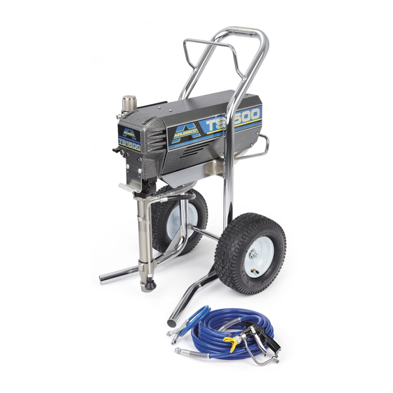
Airless Paint Sprayer
For application of architectural paints and coatings. For professional use only.
Airlessco - TS1500 (24F573) Series B
3300 psi (22.8 MPa, 228 bar) Maximum Working Pressure
Important Safety Instructions
Read all warnings and instructions in this
manual. Save these instructions.
Related Manuals
Gun Manual 3A0413
3A1183C
EN
ti17342a
Advertisement
Table of Contents

Related Manuals for AIRLESSCO TS1500 (24F573) B Series


Summary of Contents for AIRLESSCO TS1500 (24F573) B Series
- Page 1 3A1183C Airless Paint Sprayer For application of architectural paints and coatings. For professional use only. Airlessco - TS1500 (24F573) Series B 3300 psi (22.8 MPa, 228 bar) Maximum Working Pressure Important Safety Instructions Read all warnings and instructions in this manual.
- Page 2 Warnings Warnings The following warnings are for the setup, use, grounding, maintenance, and repair of this equipment. The exclama- tion point symbol alerts you to a general warning and the hazard symbols refer to procedure-specific risks. When these symbols appear in the body of this manual, refer back to these Warnings. Product-specific hazard symbols and warnings not covered in this section may appear throughout the body of this manual where applicable.
- Page 3 Warnings WARNING WARNING WARNING WARNING FIRE AND EXPLOSION HAZARD Flammable fumes, such as solvent and paint fumes, in work area can ignite or explode. To help prevent fire and explosion: • Do not spray flammable or combustible materials near an open flame or sources of ignition such as cigarettes, motors, and electrical equipment.
- Page 4 • Do not kink or over-bend the hose. • Do not expose the hose to temperatures or to pressures in excess of those specified by Airlessco. • Do not use the hose as a strength member to pull or lift the equipment.
- Page 5 Warnings WARNING WARNING WARNING WARNING MOVING PARTS HAZARD Moving parts can pinch, cut or amputate fingers and other body parts. • Keep clear of moving parts. • Do not operate equipment with protective guards or covers removed. • Pressurized equipment can start without warning. Before checking, moving, or servicing equipment, follow the Pressure Relief Procedure and disconnect all power sources.
-
Page 6: Component Identification
Component Identification Component Identification PRIME ti17939a PRESSURE ti17343a Power switch Turns sprayer ON and OFF Pressure Control Knob Adjusts pressure. Turn clockwise to increase pressure and counterclockwise to decrease pressure. Prime/Pressure Relief Valve Primes pump and relieves pressure from gun, hose and tip. Prime/Pressure Relief Valve Closed Pressurizes system when closed. -
Page 7: Operation
Operation Operation Setup Prime and Flush Storage Fluid NOTICE The equipment was tested with lightweight oil, which is left in the fluid passages to protect parts. To avoid contaminating your fluid with oil, flush the • To reduce the risk of static sparking, fire or equipment with a compatible solvent before using explosion which can result in serious bodily injury the equipment for the first time. - Page 8 Operation instruction manual provided with gun for safety fea- 8. Allow the pump to operate until clean solvent comes tures and how to engage the trigger lock. from the gun. 9. Release the trigger and engage the gun trigger lock. 10.
-
Page 9: Adjusting The Pressure
• To reduce the risk of injection, never hold your solvent such as mineral spirits or Graco or Airlessco hand, body, fingers or hand in a rag in front of the Pump Armor. -
Page 10: Regular Maintenance
2. Keep displacement pump packing nut/wet cup 1/3 Motor Brushes full of Airlessco Throat Seal Oil at all times. The TSO helps protect the packings and rod. Motor brushes need periodic inspection and replace- ment as wear indicates. -
Page 11: Replacement Of Belt/Belt Adjustment
Maintenance Replacement of Belt/Belt Servicing the Fluid Pump Adjustment NOTE: Before disassembling the sprayer refer to Trou- bleshooting to try and resolve the problem. NOTE: The Cog Belt System does not require align- ment. When upper sheave is placed on motor shaft it is Fluid Pump Disconnect pushed on until a positive stop is reached. - Page 12 Maintenance Fluid Pump Reinstall 1. Loosen the packing nut and extend piston rod to 4. Remove the retaining ring from the packing nut and fully up position. Slip sleeve over the piston rod. insert into coupling halves. ti15994a 2. Insert one of the retaining rings through the packing nut and rest the sleeve on top of it.
- Page 13 Pressure Relief Procedure whenever you: and cylinder to your Graco/Airlessco distributor for removal. • are instructed to relieve the pressure • stop spraying 1.
- Page 14 Maintenance 2. Unscrew intake valve from cylinder. 5. Remove piston rod from sleeve, or remove sleeve from cylinder. 7572a 7569a 6. Unscrew piston valve from piston rod. Clean and 3. Disassemble intake valve. Clean and inspect. O-ring inspect parts. The piston has a special thread lock- (227) may require a pick for removal.
- Page 15 Maintenance 8. Remove throat packings and glands from cylinder. ® 2. Install ball (206) in piston rod. If Loctite is applied Discard throat packings and glands. to piston valve threads, ensure that none gets on ball. 75736b 7575a Assembling the pump 3.
- Page 16 Maintenance leather packings (223) (note orientation). Place NOTICE female gland (224) in top of cylinder. Seat packings. Do not slide piston assembly into top of sleeve as this may damage piston packing. 7. Slide piston assembly into bottom of sleeve. 7577a 7573f 8.
-
Page 17: Replacement Of Electrical Components
Maintenance 10. Reassemble intake valve with new O-ring (227), Replacement of Electrical seat (212) and ball (214), Seat may be flipped over Components and used on other side. Clean seat thoroughly. Always unplug the electrical cord before servicing the machine. Pressure Control Assembly (Electrical Control Board) 1. -
Page 18: On-Off Toggle Switch
Maintenance On-Off Toggle Switch Liquid Crystal Display (LCD) 1. Lower the pressure control assembly as described 1. Ensure the power switch is OFF and the machine is above. unplugged. 2. Disconnect the two wires on the toggle switch. 2. Detach the pressure control assembly from the frame by unscrewing the two screws. -
Page 19: Troubleshooting
Troubleshooting Troubleshooting General Problem Cause Solution Unit doesn’t prime Airleak due to loose suction nut Tighten suction nut. Airleak due to worn o-rings Replace o-ring on suction seat and o-ring below suction seat. Stuck or fouled balls Service inlet and outlet valves. Prime/Pressure Relief valve not Clean or replace Prime/Pressure Relief Valve opening... - Page 20 Troubleshooting Problem Cause Solution Motor Remove the motor brush covers and turn the machine ON. Set the potentiometer (POT) at maximum pressure and check for DC voltage across both brush terminals. It should read greater than 80 volts DC. If you have DC voltage, turn the machine off and unplug it from the wall.
-
Page 21: Pressure Control Repair
Troubleshooting Pressure Control Repair Motor Control Board Diagnostics 1. For sprayers with digital display, seeDigital Display Messages, page 22 2. Remove screws and cover. Relieve pressure and unplug sprayer before servicing control board. See Pressure Relief Procedure, 3. Turn ON/OFF switch ON. page 13. -
Page 22: Digital Display Messages
Troubleshooting Digital Display Messages No display does not mean that spayer is not pressurized. Relieve pressure before repair. See Pressure Relief Procedure, page 13 DISPLAY SPRAYER OPERATION INDICATION ACTION No Display Sprayer stops. Power is Loss of power. Check power source. Relieve not applied. -
Page 23: Airless Spray Gun
Troubleshooting Airless Spray Gun Problem Cause Solution Coarse spray Low pressure Increase the pressure Excessive fogging (overspray) High pressure Reduce the pressure to satisfactory pattern distribution. Material too thin Use less thinner Pattern too wide Spray angle too large Use smaller spray angle tip Pattern too narrow Spray angle too small Use larger spray angle tip (if coverage is OK,... - Page 24 Troubleshooting Problem Cause Solution Tip clogs continually Debris in paint Thoroughly strain the paint before use Gun filter missing Do not operate without inlet strainer Coarse filter mesh Do not operate without inlet strainer Test the Pattern Spotty Pattern, Good, Full Increase Pressure ti15991a 3A1183C...
-
Page 25: Optional Filter Kit
Parts Parts Optional Manifold Kit (301440) Ref. Part Description Qty. 866123 FILTER, ASSY 867188 FITTING, ELBOW STREET 90 3/8 867309 FITTING, NIPPLE, 3/8 NPT to 1/4 866445 SPACER, .377 ID x .40 LG AL 305140 BRACKET - FILTER 867534 SCREW 5/16-18 x 1.00 PH HD (not shown) 331103 WASHER .562 .250 .060 .ST 121112 SCREW, CAP, SOCKET HEAD... - Page 26 Parts Frame Parts Diagram ti 17876a ti17476a Ref Part Description Qty. Ref Part Description Qty. 256219 POTENTIOMETR,ASSEMBLY 342425▲ LABEL - HIGH VOLTAGE 866049 CABLE,ASSY 9” LG LABEL,DESIGNATION 110637 SCREW,MACH,PANHEAD 867791 FRAME,CART 867252 GROMMET 301134 PLUG,NEOPRENE HSE3850 HOSE, 3/8” x 50 143029 COLLAR,SCREW,SET (SPECIAL ID) 255439...
-
Page 27: Motor And Drive
Parts Motor and Drive ti17477a 3A1183C... - Page 28 FRONT 66 867704 WASHER,PLAIN, 5/16 NOMINAL 12 16F597 LABEL,AIRLESSCO, TS1500, 67 111303 NUT,HEX RIGHT 68 140029 WASHER,PLAIN 13 16F598 LABEL,AIRLESSCO, TS1500, LEFT 69 100307 NUT,HEX 41 189920 STRAINER,(1-11 1/2 NPSM) 70 301044 SCREW,MODIFIED 42 198542 CLIP,SPRING 71 301099 RETAINER,5/8-18 43 193031...
- Page 29 Parts TS1500 Pump Parts Diagram Ref. Part Description Qty. 196753 HOUSING, VALVE, INTAKE CYLINDER, PUMP 193032 NUT. PACKING 248210 SLEEVE, CYLINDER 24E353 ROD, PISTON 240150 VALVE, PISTON 15C998 WASHER, BACKUP 183185 GLAND, PACKING, FEMALE 1 193125 PACKING, VEE 15E329 PACKING, VEE 183178 PACKING, GLAND, MALE BALL, BEARING 107098 PACKING, O-RING...
- Page 30 Parts Prime/Pressure Relief Valve (865719) Ref. Part Description Qty. 865013 ADAPTER,VALVE 15G563 HANDLE, VALVE 867759 CONNECTOR, MALE, 3/8 TUBE x 1/8 PIPE 116424 NUT, CAP ti16004a Suction Assembly - 55 Gallon (119087) ti16039a Ref. Part Description Qty. Ref. Part Description Qty.
-
Page 31: Control Parts Diagram
Parts Control Parts Diagram ti17478a Ref. Part Description Qty. Ref. Part Description Qty. 865013 ADAPTER,VALVE 342425▲ LABEL - HIGH VOLTAGE 865719 VALVE,DRAIN,ASSY 24B599 TRANSDUCER,PRESSURE 15G563 HANDLE,VALVE CONTROL 116424 NUT,CAP 866049 CABLE,ASSY 9” LG 114708 SPRING,COMPRESSION 110637 SCREW,MACH,PANHEAD 193709 SEAT,VALVE 557391 PLUG,DRYSEAL 1/4 NPTF 193710 SEAL,SEAT,VALVE... -
Page 32: Electrical System
Parts Electrical System Black ON/OFF Black Switch Power Plug Black White Green Red (+) Black (-) from Motor 2 x White ti12471a Ref. Part Description Qty. Ref. Part Description Qty. 331168 ELECTRICAL CORD110V 24B599 SENSOR 301083 TOGGLE SWITCH 256219 POTENTIOMETER PRESSURE CONTROL ASSY 110V 3A1183C... -
Page 33: Technical Data
Technical Data Technical Data Power requirements ........100 AC, 50 hz, 11A, 1 phase Generator required . -
Page 34: Airlessco Standard Warranty
With the exception of any special, extended, or limited warranty published by Airlessco, Airlessco will, for a period of twelve months from the date of sale, repair or replace any part of the equipment determined by Airlessco to be defective.
Need help?
Do you have a question about the TS1500 (24F573) B Series and is the answer not in the manual?
Questions and answers