Table of Contents
Advertisement
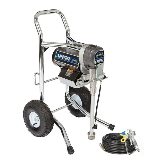
Operation/Repair/Parts
LP 400/500/600/700
Mustang 5100/8100
Airless Paint Sprayer
For application of architectural paints and coatings. For professional use only. Not
approved for use in European explosive atmosphere locations.
3000 psi (20.7 MPa, 207 bar) Maximum Working Pressure
Important Safety Instructions
Read all warnings and instructions in this manual. Save these instructions.
For model information, see page 2.
Related Manuals
Gun Manual
312363 - English
312364 - Spanish
312365 - French
3A1185H
EN
Advertisement
Table of Contents


Need help?
Do you have a question about the LP 400 and is the answer not in the manual?
Questions and answers