Table of Contents
Advertisement
Quick Links
Operation/Repair/Parts
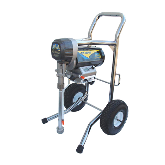
EZ Rent 570/700
Airless Paint Sprayer
For application of architectural paints and coatings. Not approved for use in European
explosive atmosphere locations.
3000 psi (20.7 MPa, 207 bar) Maximum Working Pressure
IMPORTANT SAFETY INSTRUCTIONS
Read all warnings and instructions in this manual. Be familiar with
the controls and the proper usage of the equipment. Save these
instructions.
Airlessco EZ Rent 570 Hi Boy
Airlessco EZ Rent 570 Lo Boy
Airlessco EZ Rent 700 Hi Boy
Airlessco EZ Rent 700 Lo Boy
Model
Part Number
24F585
16M528
16M526
24F586
24F588
16M529
16M527
24F587
Volt-
SERIES
age
120V
B
110V
A
240V
A
120V
C
120V
B
110V
A
240V
A
120V
C
3172585
Certified to CAN/CSA C22. No. 68
Conforms to UL 1450
3A1182G
EN
ti16138a
ti16139b
Advertisement
Table of Contents

Related Manuals for AIRLESSCO Airlessco EZ Rent 570 Hi Boy


Summary of Contents for AIRLESSCO Airlessco EZ Rent 570 Hi Boy
- Page 1 Read all warnings and instructions in this manual. Be familiar with the controls and the proper usage of the equipment. Save these instructions. Model Part Number Volt- SERIES 24F585 120V Airlessco EZ Rent 570 Hi Boy 16M528 110V ti16138a 16M526 240V Airlessco EZ Rent 570 Lo Boy 24F586 120V...
- Page 2 Warnings Warnings The following warnings are for the setup, use, grounding, maintenance, and repair of this equipment. The exclama- tion point symbol alerts you to a general warning and the hazard symbols refer to procedure-specific risks. When these symbols appear in the body of this manual or warning labels, refer back to these Warnings. Product-specific hazard symbols and warnings not covered in this section may appear throughout the body of this manual where applicable.
- Page 3 Warnings WARNING WARNING WARNING FIRE AND EXPLOSION HAZARD Flammable fumes, such as solvent and paint fumes, in work area can ignite or explode. To help prevent fire and explosion: • Do not spray or clean with materials having flash points lower than 100° F (38° C). Use only non-flam- mable or water-based materials, or non-flammable paint thinners.
- Page 4 Warnings WARNING WARNING WARNING SKIN INJECTION HAZARD High-pressure spray is able to inject toxins into the body and cause serious bodily injury. In the event that injection occurs, get immediate surgical treatment. • Do not aim the gun at, or spray any person or animal. •...
- Page 5 Warnings WARNING WARNING WARNING TOXIC FLUID OR FUMES HAZARD Toxic fluids or fumes can cause serious injury or death if splashed in the eyes or on skin, inhaled, or swallowed. • Read Safety Data Sheet (SDS) to know the specific hazards of the fluids you are using. •...
-
Page 6: Component Identification
Component Identification Component Identification ti17301a Power switch Turns sprayer ON and OFF Pressure Control Knob Adjusts pressure. Turn clockwise to increase pressure and coun- terclockwise to decrease pressure. Prime/Pressure Relief Valve Primes pump and relieves pressure from gun, hose and tip. Prime/Pressure Relief Valve Open Posi- Relieves pressure from gun, hose and tip and primes the unit tion... -
Page 7: Operation
Operation Operation Pressure Relief Procedure The valve handle can move both clockwise and counter- clockwise and can face different directions. 5. Re-engage gun trigger lock and close Prime/Pres- Follow this Pressure Relief Procedure whenever you sure Relief Valve. When in the closed position there stop spraying and before cleaning, checking, servicing, is only a very slight gap or transporting equipment. -
Page 8: Prime And Flush Storage Fluid
Operation Flushing Fill the Packing Nut/Wet Cup 1. Fill the Packing Nut/Wet Cup with 5 drops of Air- lessco Throat Seal Oil (TSO). • To reduce the risk of static sparking, which can cause fire or explosion, always hold a metal part of the gun firmly against the metal pail when flush- ing. - Page 9 Operation Startup 6. Turn the engine ON/OFF switch to ON. 7. Point the gun into the metal pail and hold a metal 1. Prepare the material according to the material man- part of the gun firmly against the pail. Maintain firm ufacturer’s recommendations.
-
Page 10: Adjusting The Pressure
(also called spray tip when cleaning or checking for a cleared white spirit) or Graco or Airlessco Pump Armor. tip. Always point the gun toward the ground or into a waste container when checking to see if the tip is •... -
Page 11: Daily Maintenance
Keep displacement pump packing nut/wet cup 1/3 full of pressure. (The pump has to cycle fast with no pres- Airlessco Throat Seal Oil at all times. The TSO helps sure in the pump). Run the pump for 20 minutes and protect the packings and rod. - Page 12 7. Tighten packing nut clockwise until resistance is felt against the Belleville Springs, go 3/4 if a turn more. Put five drops of Airlessco Throat Seal Oil in the packing nut. 8. Run the machine at full pressure for several min- utes.
-
Page 13: Packing Replacement Procedures
Maintenance Packing Replacement 7. Take the spacer (15) and slide over the top of the piston (14). Procedures 8. Take three spring washers (16) and slide over the top of the piston (14) in the following order: Disassembly of the Fluid Pump •... -
Page 14: Gear And Pump Assembly
Maintenance Gear and Pump Assembly 18. Reinstall Fluid Pump, page 12. Servicing Gear box Assembly 1. Remove fluid pump. See Fluid Pump Disconnect, page 11. 2. Remove frame from the gearbox by loosening the four mounting screws. 3. Separate cover assembly (14) from box by remov- 23 23 23 23 ing bolts (1) from front of cover and back of box and shoulder bolts (2) from front of cover and back of... -
Page 15: Replacement Of Electrical Components
Maintenance Replacement of Electrical Sensor Components 1. Remove the four screws, heatsink, and lower the pressure control assembly. 2. Disconnect sensor lead from the board. 3. Unscrew sensor by holding sensor with 3/4” wrench. To avoid electric shock, always unplug the electrical cord before servicing the machine. -
Page 16: On-Off Toggle Switch
Maintenance On-Off Toggle Switch Liquid Crystal Display (LCD) 1. Lower the pressure control assembly as described 1. Lower pressure control assembly as described above. above. 2. Disconnect the two wires on the toggle switch. 2. Unscrew the two nuts (M3) and remove LCD Dis- play assembly. -
Page 17: Troubleshooting
Troubleshooting Troubleshooting General Problem Cause Solution Unit doesn’t prime Airleak due to loose suction nut Tighten suction nut. Airleak due to worn o-rings Replace o-ring (108526) on suction seat and o-ring (867370) below suction seat. Airleak due to hole in suction Replace suction hose hose Stuck or fouled balls... - Page 18 Troubleshooting Problem Cause Solution Machine does not start Motor Remove the motor brush covers and turn the machine ON. Set the potentiometer (POT) at maximum pressure and check for DC voltage across both brush terminals. It should read greater than 80 volts DC. If you have DC voltage, turn the machine off and unplug it from the wall.
-
Page 19: Pressure Control Repair
Troubleshooting Pressure Control Repair Motor Control Board Diagnostics 1. For sprayers with digital display, see Digital Dis- play Messages, page 20 2. Remove screws and cover. 3. Turn ON/OFF switch ON. Relieve pressure and unplug sprayer before servicing control board. See Pressure Relief Procedure, page 4. - Page 20 Troubleshooting Digital Display Messages No display does not mean that sprayer is not pressur- ized. Relieve pressure before repair. See Pressure Relief Procedure, page 7 DISPLAY SPRAYER OPERATION INDICATION ACTION No Display Sprayer stops. Power is not Loss of power. Check power source.
-
Page 21: Airless Spray Gun
Troubleshooting Airless Spray Gun Problem Cause Solution Coarse spray Low pressure Increase the pressure Excessive fogging (overspray) High pressure Reduce the pressure to satisfactory pattern dis- tribution. Material too thin Use less thinner Pattern too wide Spray angle too large Use smaller spray angle tip Pattern too narrow Spray angle too small... -
Page 22: Servicing The Inlet Valve
Troubleshooting Servicing the Inlet Valve Servicing Gear Box Assembly 1. Un-thread and remove suction nut from the fluid pump body (8). 2. Remove suction seat (12), O-ring (11), suction ball Ensure cover guard is in place before operating. (10) and ball guide (9). 1. -
Page 23: Manifold Filter
Parts Parts Manifold Filter (866480) Ref. Part Description 867145 COVER 301356 SPRING 867377 O-RING 867214 FILTER 60 MESH 867647 SUPPORT 867077 BASE 867420 PLUG 867309 NIPPLE 3/8”M x 1/4”M 557391 PLUG 1/4” ti16052a 3A1182G... - Page 24 Parts Lo-Boy Frame Parts Diagram Ref. Part Description 331491 MOTOR 331171 FRAME 867736 WHEEL 143029 COLLAR,SCREW,SET 331048 BOOT,RUBBER BOOT HSE1450 HOSE,PAINT HOSE 1/4X50’ 289316 GUN,SPRAY, 009 124 121112 SCREW,CAP, SOCKET HEAD 127* 867551 SCREW 6-32X1.25 PH PN HD 128* 867329 NUT,NUT 6-32 X .109 TOP LOCK 129* 15B870 130 305039...
- Page 25 Parts Hi-Boy Frame Parts Diagram ti17439a Ref. Part Description MOTOR 331491 110/120V 331493 230/240V 331273 FRAME 16F551 FASTENER,THREAD,EXTERNAL 866356 SPACER,SPACER .75 LG PVC 867736 WHEEL 143029 COLLAR,SCREW,SET 331048 BOOT,RUBBER BOOT HSE1450 HOSE,PAINT HOSE 1/4X50’ 289316 GUN,SPRAY, 009 3A1182G...
-
Page 26: Control Parts Diagram
Parts Control Parts Diagram ti17482a Ref. Part Description Ref. Part Description CONNECTOR,ELECTRICAL MOTOR 867800 TERMINAL BOX WELDMENT 331296 GUARD,SPLASH 117281 SPACER,#6 X .312 101* 301083 SWITCH,TOGGLE 867816 SCREW,MACH,PHILLIPS FLAT HD 102* 301150 BOOT,RUBBER,BLACK DISPLAY,LCD 103* 867797 GASKET,COVER LP 867731 WASHER,PLAIN-1/8IN.IDX5/16IN.OD 15C973 GASKET, 867817... -
Page 27: Motor And Drive Parts Diagram
Parts Motor and Drive Parts Diagram ti17840e 3A1182G... - Page 28 Parts Motor and Drive Parts List Ref. Part Description 331062 SPRING,RET. SPRING Ref. Part Description 867539 SCREW,5/16-18 X3.75 HX HD 868016 COVER,COVER - GUARD MOTOR 866338 SCREW, SHOULDER 331491 110/120V 107445 SCREW, CAP 331493 230/240V 557391 PLUG 331785 FAN (not shown) 866428 PRESSURE RELIEF VALVE 331786...
-
Page 29: Packing Replacement
Parts Packing Replacement Ref. Part Description 331014 MALE GLAND 331016 PACKING POLYETHYLENE 331308 FEMALE ADAPTOR 331011 FLUID PUMP BODY 331029 SUCTION BALL GUIDE 331030 SUCTION BALL 23 23 23 23 108526 O-RING 331292 SUCTION SEAT (HI-BOY) 2 2 2 331034 SUCTION NUT 331314 OUTLET SEAT RETAINER 18 18 18 22 22... -
Page 30: Suction Assemblies
Parts Gearbox Sleeve Bearing Replacement Ref. Part Description 331061 SLEEVE BEARING 331103 WASHER 331197 SCREW When replacing item (1), cover outside of sleeve with 6 drops of Loctite 246 prior to inserting into cover assembly. ti16059a Suction Assemblies Hi-Boy Chassis (331284) Lo-Boy and Carry Chassis (865717) ti16061a ti16062a... - Page 31 Parts Electrical System - EZ Series Black ON/OFF Black Switch Power Plug Black White Green Black (+) Black (-) from Motor 2 x Red ti2471b Ref.Part Description Ref. Part Description ELECTRICAL CORD110V PRESSURE CONTROL ASSEMBLY 331163 120V 243222 SENSOR 118046 110V 256219 POTENTIOMETER 301101 240V 342423 LABEL,Warning...
-
Page 32: Electrical Components
Parts Electrical Components ti16066a Ref. Part Description Ref. Part Description 867816 SCREW 117281 SPACER 867804 LABEL, PRESSURE CONTROL 1 867817 867731 WASHER 867798 WINDOW LCD DISPLAY (PSI) 867821 LCD DISPLAY KIT(PSI) Includes 1, 3, 4, 5, 7 3A1182G... - Page 33 STEP 2 Check gun/hose connections to make sure they are tight. Lock gun trigger lock (Airlessco gun shown). Plug into 3 pronged grounded electrical outlet. Extension cord must be 3 wire, 12 gauge. Do not coil cord. ti16069a STEP 3 Put pump suction tube into bucket of paint.
- Page 34 Parts Cleaning • Always use low pressure in the cleaning process. • Always remove spray tip before cleaning - AFTER following the Pressure Relief Procedure! • Use a metal bucket for cleaning and maintain firm metal to metal contact to gun to the bucket. Tools and Equipment Needed Soft bristle brush, clean-up rags.
-
Page 35: Technical Data
Technical Data Technical Data EZ Rent 570/700 Metric Power requirements 120V AC, 60 hz, 11A, 1 phase 230V AC, 50/60 hz, 7.5A, 1 phase Generator required 3000 w minimum Maximum working pressure 3000 psi 21 MPa, 207 bar Maximum delivery EZ Rent 570 0.85 gpm 3.2 lpm... -
Page 36: Airlessco Standard Warranty
With the exception of any special, extended, or limited warranty published by Airlessco, Airlessco will, for a period of twelve months from the date of sale, repair or replace any part of the equipment determined by Airlessco to be defective.
Need help?
Do you have a question about the Airlessco EZ Rent 570 Hi Boy and is the answer not in the manual?
Questions and answers