Table of Contents
Advertisement
Quick Links
Operation
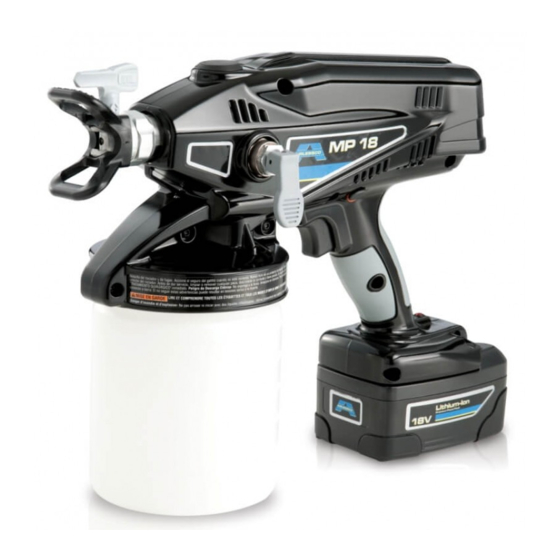
MP18 Cordless Paint Sprayer
U.S. Patent 6,619,569; D630,708S and other patents pending
Community Design Registration #01228255; India Patent No. 230058
China Patent No. ZL201030238948.3
- For portable spray applications of water-based architectural paints and coatings only -
- Not approved to European explosive atmosphere requirements -
IMPORTANT SAFETY INSTRUCTIONS
Read all warnings and instructions in this
manual. Save these instructions.
Model 24E822
Maximum Working Pressure 2000 psi (137 bar, 13.7 MPa)
Use only water-based materials. Do not use materials which state "FLAMMABLE" on the packaging. For
more information about your material, request MSDS from distributor or retailer.
Spraying certain materials may cause static build-up in the sprayer that can result in static shock to
the user. If this occurs, first ensure the material has a flash point greater than 100° F (38° C) and does not
state that it is FLAMMABLE anywhere on the package. If still feeling a static shock, the material likely con-
tains a non-mineral spirits fluid such as, but not limited to, xylene, toluene, or naphtha, which can build up
static. Switch to an alternative material.
WARNING
WARNING
WARNING
WARNING
3A1266B
ENG
ti14773a
Advertisement
Table of Contents

Subscribe to Our Youtube Channel
Related Manuals for AIRLESSCO MP18


Summary of Contents for AIRLESSCO MP18
- Page 1 Operation MP18 Cordless Paint Sprayer 3A1266B U.S. Patent 6,619,569; D630,708S and other patents pending Community Design Registration #01228255; India Patent No. 230058 China Patent No. ZL201030238948.3 - For portable spray applications of water-based architectural paints and coatings only - - Not approved to European explosive atmosphere requirements -...
-
Page 2: Table Of Contents
(Fine-Finish Optimizer) ....9 Airlessco Standard Warranty ....28 Sprayer Setup . -
Page 3: Warnings
Warnings Warnings The following warnings are for the setup, use, maintenance, and repair of this equipment. The exclamation point symbol alerts you to a general warning and the hazard symbols refer to procedure-specific risks. When these symbols appear in the body of this manual, refer back to these Warnings. - Page 4 Do not short-circuit the terminals of the battery. • Keep the battery away from fire. • Charge only with Airlessco approved charger as listed in this manual. • Do not expose to heat above 170° F (80° C). • Do not expose battery to water or rain.
-
Page 5: Component Identification
Component Identification Component Identification ti15479a Prime/Relief Valve Cordless Paint Sprayer Lithium Ion Premium Power Battery Charger Sprayer Hook Material Cup Liners (5 included) Outlet Valve Repair Access Shoulder Strap Spray Tip/Guard Assembly (211, 411, 515 included) Lithium Ion Premium Power Battery (2 included) Tip Filter (*Reverse Threaded) Battery Release Button Standard Suction Tube (sprays ceilings and walls) -
Page 6: Common Procedures
Common Procedures Common Procedures Pressure Relief Procedure Spray Tip Position Do not operate or spray near children. Do not aim the Always perform Pressure Relief Procedure before sprayer at, or spray any person or animal. Keep hands adjusting spray tip position. and other body parts away from the front of the sprayer. -
Page 7: Charging The Battery
Batteries may leak, explode, cause burns or cause an explosion if mishandled. To reduce the risk of electric shock, only use Airlessco batteries with the Airlessco charger. Do not insert any Batteries are initially 50% charges to provide optimum foreign objects into the adapter cup. -
Page 8: Setup
Setup Setup When spraying ceilings, the inlet of the suction tube should be aimed at the back of the material cup (towards the trigger). Use only water-based materials. Do not use materi- als which state “FLAMMABLE” on the packaging. For more information about your material, request MSDS from distributor or retailer. -
Page 9: Spraying Stains Or Clear Coats (Fine-Finish Optimizer)
Setup Spraying Stains or Clear Coats 2. Put prime/relief valve to UP position, then hold trig- ger in for 10 seconds. (Fine-Finish Optimizer) The Fine-Finish Optimizer should be installed and used when spraying thin material such as stain or clear coats. The Fine-Finish Optimizer restricts the material flow resulting in a finer quality finish. -
Page 10: Materials
Setup Materials Starting a New Job (or Refilling the Cup) Engage trigger lock and put prime/relief valve UP to release pressure. Use only water-based materials. Do not use materi- als which state “FLAMMABLE” on the packaging. For more information about your material, request MSDS ti14994a ti14999a from distributor or retailer. -
Page 11: Install Tip/Guard Assembly (If Not Installed)
Setup Install Tip/Guard Assembly Shoulder Strap Installation (if not installed) 1. Attach the metal eyelet to the back of the sprayer. Reversible Tip Selection Chart MATERIALS *Thin Medium Heavy Thin stains, Enamels, solid Heavy latex semi-transparent stains stains, thin latex 211, 411 213, 413 315, 515... -
Page 12: Basic Spraying Techniques
Setup Basic Spraying Techniques Triggering Sprayer NOTE: Use a piece of scrap cardboard to practice these To achieve even spraying, pull trigger after starting the basic spraying techniques before you begin spraying the stroke. Release trigger before the end of the stroke. surface. -
Page 13: Unclogging Spray Tip/Guard Assembly
Unclogging Spray Tip/Guard Assembly Unclogging Spray 5. Disengage trigger lock, put prime/relief valve DOWN to spray position, and resume spraying. Tip/Guard Assembly ti14995a ti15425a Do not operate or spray near children. Do not aim the sprayer at, or spray any person or animal. Keep hands 6. -
Page 14: Shutdown And Cleaning
Shutdown and Cleaning Shutdown and Cleaning 2. Remove material cup and properly dispose cup liner or excess material. NOTICE Failure to properly clean sprayer after each use will result in hardened materials, damage to the sprayer, and the warranty will no longer be valid. Flushing Sprayer ti15000a 3. - Page 15 Shutdown and Cleaning 6. Disconnect trigger lock and trigger sprayer for 10. Engage trigger lock and put prime/relief valve UP to approximately 15 seconds. Engage trigger lock. release pressure. ti14994a ti14994a 11. Remove material cup and discard used fluid. 7. Discard contaminated fluid and refill with appropri- 12.
-
Page 16: Cleaning Sprayer Exterior
Storage Cleaning Sprayer Exterior 2. Thread cup into sprayer, put prime/relief valve to UP position and squeeze sprayer trigger for approxi- mately 10 seconds. • Wipe paint off outside of sprayer using a soft cloth moistened with water or flushing fluid. Do NOT submerge the sprayer. -
Page 17: Replacement Parts And Kits
211 (included with sprayer) 16D561 Material Cup (1.5 L) cover and seal PST213 24E377 Shoulder Strap PST315 16G746 Label, Sprayer, MP18, Main PST411 411 (included with sprayer) 16G747 Label, Sprayer, MP18, Front PST413 24D425 Lid with gasket (not shown) PST515... -
Page 18: Repair Kit
Repair Kit Repair Kit 4. Use tool (supplied) to loosen and remove outlet valve fitting. Outlet Valve Fitting NOTE: Before doing any repair to pump, perform Flushing Sprayer procedure, page 14. ti15506a Removal 1. Engage trigger lock and pull relief valve UP to Installation release pressure. -
Page 19: Alternate Priming Method
Alternate Priming Method Alternate Priming Method 4. Hold sprayer above sink or waste area, disengage the trigger lock, and quickly trigger sprayer until material comes out of the drain tube. 1. Engage trigger lock and put prime/relief valve UP to release pressure. -
Page 20: Inlet Valve Cleaning
Alternate Priming Method Inlet Valve Cleaning Removal Installation NOTE: Before installing, make sure o-ring (c) is installed 1. Engage trigger lock and pull relief valve UP to on inlet valve (b). release pressure. 1. Place inlet valve (b) with spring (a) on top of inlet fit- ting (d). -
Page 21: Troubleshooting
Troubleshooting Troubleshooting Check everything in this Troubleshooting Table before you bring the sprayer to an authorized service center. Problem Cause Solution Sprayer makes no sound when Trigger is locked. Disengage trigger lock. See page 6. trigger is pulled Status Indicator Light is solid RED when Replace with charged battery and place triggering, indicating that the battery old battery in charger or allow the battery... - Page 22 Troubleshooting Problem Cause Solution Sprays with poor results Tip is partially clogged See Unclogging Tip/Guard Assembly, page 13. Tip is not in correct position Rotate tip to SPRAY position. Incorrect tip for application of See Reversible Tip Selection Chart, material. page 11.
- Page 23 Troubleshooting Problem Cause Solution Spray pattern is too wide: Sprayer is too far away from target surface. Move sprayer closer to surface. Incorrect tip for application of material. See Reversible Tip Selection Chart, page 11. ti15527a Spray pattern “spits” at the end: Excess material has accumulated on Spray See Shutdown and Cleaning, page 14.
-
Page 24: Technical Data
Technical Data Technical Data Sprayer: Maximum working pressure 2000 psi (137.8 bar, 13.7 MPa) Weight 6.32 lb (2.87 kg) Dimensions: Length 13.25 in. (33.6 cm) Width 5.0 in. (12.7 cm) Height 10.375 in. (26.4 cm) Storage temperature range ◆❖ 32° to 122° F (0° to 50° C) Operating temperature range ✔... -
Page 25: Notes
Notes Notes 3A1266B... - Page 26 Notes Notes 3A1266B...
- Page 27 Notes Notes 3A1266B...
-
Page 28: Airlessco Standard Warranty
With the exception of any special, extended, or limited warranty published by Airlessco, Airlessco will, for a period of twelve months from the date of sale, repair or replace any part of the equipment determined by Airlessco to be defective.
Need help?
Do you have a question about the MP18 and is the answer not in the manual?
Questions and answers