Sun Microsystems Sun Fire V250 Administration Manual
Hide thumbs
Also See for Sun Fire V250:
- Parts replacement manual (62 pages) ,
- Installation manual (50 pages)
Table of Contents
Advertisement
Quick Links
Download this manual
See also:
Installation Manual
Advertisement
Table of Contents

Related Manuals for Sun Microsystems Sun Fire V250


Summary of Contents for Sun Microsystems Sun Fire V250
- Page 1 Sun Fire V250 Server Administration Guide Sun Microsystems, Inc. 4150 Network Circle Santa Clara, CA 95054 U.S.A. 650-960-1300 Part No. 817-0900-10 September 2003, Revision A Send comments about this document to: docfeedback@sun.com...
- Page 2 Copyright 2003 Sun Microsystems, Inc., 4150 Network Circle, Santa Clara, California 95054, Etats-Unis. Tous droits réservés. Sun Microsystems, Inc. a les droits de propriété intellectuels relatants à la technologie incorporée dans le produit qui est décrit dans ce document. En particulier, et sans la limitation, ces droits de propriété intellectuels peuvent inclure un ou plus des brevets américains énumérés à...
-
Page 3: Table Of Contents
Contents Introduction 1 Overview of the Server 2 Features 2 Door Features 3 Server Status Indicators 3 Front Panel Features 3 On/Standby Button 4 Controlling Server Power 5 Hard Disk Drives 6 DVD-ROM Drive 6 System Configuration Card 6 Operation Mode Switch 9 Back Panel Features 11 Network Connectors 12 Serial Ports 12... - Page 4 System Prompts 13 Removing and Replacing Components 15 Replaceable Components 16 Lifting the Server 16 Avoiding Electrostatic Discharge 16 To Avoid Electrostatic Discharge While Working on the Front of the Server 16 Controlling Server Power 17 To Turn Server Power On 18 To Turn Server Power Off 18 Swapping the System Configuration Card Between Servers 19 To Swap the System Configuration Card Between Servers 19...
- Page 5 Sun Management Center 33 Sun Management Center 34 How Sun Management Center Works 34 Other Sun Management Center Features 35 Using Sun Management Center 35 Hardware Diagnostic Suite 36 When to Run Hardware Diagnostic Suite 36 Requirements for Using Hardware Diagnostic Suite 36 Sun VTS 39 SunVTS 40 SunVTS Software and Security 41...
- Page 6 To Run Solaris System Information Commands 66 Recent Diagnostic Test Results 67 To View Recent Test Results 67 OpenBoot Configuration Variables 67 To View And Set OpenBoot Configuration Variables 68 Automatic Server Restart 69 Sun Fire V250 Server Administration Guide • September 2003...
- Page 7 Figures The Sun Fire V250 server 2 FIGURE 1-1 Location of On/Standby Button 4 FIGURE 1-2 Operation Mode Switch (shown in Standby Position) 10 FIGURE 1-3 Location of I/O Ports 11 FIGURE 1-4 System Prompt Flow Diagram 14 FIGURE 1-5...
- Page 8 Figures viii...
- Page 9 Tables Server Status Indicators 3 TABLE 1-1 On/Standby Button Actions and Results 5 TABLE 1-2 Explanation of Power States 5 TABLE 1-3 Hard Disk Drive Service Indicators 6 TABLE 1-4 OBP Configuration Parameters Stored On The System Configuration Card 7 TABLE 1-5 Operation Modes 10 TABLE 1-6...
- Page 10 Sun Fire V250 Server Administration Guide • September 2003...
-
Page 11: Before You Read This Book
Preface The Sun Fire V250 Server Administration Guide is intended to be used by system administrators. As well as general descriptive information about the Sun Fire V250 server, it includes detailed instructions on the following topics: Server administration Problem diagnosis... -
Page 12: Typographic Conventions
To delete a file, type rm filename. Shell Prompts Shell Prompt C shell machine-name% C shell superuser machine-name# Bourne shell and Korn shell Bourne shell and Korn shell superuser ALOM shell sc> OpenBoot PROM shell xii Sun Fire V250 Server Administration Guide • September 2003... -
Page 13: Related Documentation
Latest information Sun Fire V250 Server Product Notes 817-1003-xx Read the Sun Fire V250 Server Compliance and Safety Manual before performing any of the procedures documented in this manual. Accessing Sun Documentation Online You can view, print, or purchase a broad selection of Sun documentation, including localized versions, at: http://www.sun.com/documentation/... - Page 14 Sun Fire V250 Server Administration Guide • September 2003...
-
Page 15: Introduction
C H A P T E R Introduction This chapter describes the Sun Fire V250 server and gives an overview of its main features. It contains the following sections: “Overview of the Server” on page 2 “Door Features” on page 3 “Back Panel Features”... -
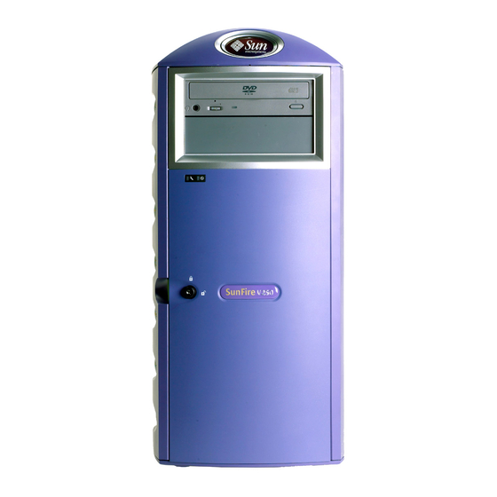
Page 16: Overview Of The Server
Overview of the Server The Sun Fire V250 server FIGURE 1-1 Features The Sun Fire V250 server has the features listed below. UltraSPARC™ IIIi processor(s) Four DDR DIMM slots per processor One 10/100/1000BASE-T autonegotiating Ethernet port One Ultra160 SCSI multimode port One RJ-45 serial port for server management Sun Fire V250 Server Administration Guide •... -
Page 17: Door Features
Sun™ Advanced Lights-Out Manager Door Features The front door of the Sun Fire V250 server is lockable to provide security. Unlock and open the door to gain access to the front-panel features. The door includes two LED indicators, visible when the door is closed, which convey the operating status of the server. -
Page 18: On/Standby Button
The only way to do that is to physically disconnect the server from its power source. On/Standby button Location of On/Standby Button FIGURE 1-2 The On/Standby button is a momentary design with two operation modes: Press and immediately release Sun Fire V250 Server Administration Guide • September 2003... -
Page 19: Controlling Server Power
Controlling Server Power For information about connecting the server to a power source and powering on the server, see the Sun Fire V250 Server Installation Guide. For information about controlling server power using software, see the ALOM Online Help. -
Page 20: Hard Disk Drives
Hard Disk Drives The Sun Fire V250 server has slots for up to eight hard disk drives. The slots accept Sun 36 GB and 73 GB LVD SCSI hard disk drives conforming to the 1-inch SCA-2 form factor. Each hard disk drive has two LED indicators associated with it. Indicator states are... -
Page 21: Table 1-5 Obp Configuration Parameters Stored On The System Configuration Card
It is essential that you store the SCC safely if you have to remove it from the server, and replace it before restarting the system. For more information, see “Swapping the System Configuration Card Between Servers” on page 19. OBP Configuration Parameters Stored On The System Configuration Card TABLE 1-5 Parameter Default... - Page 22 (never displayed) - do not set this directly Number of incorrect security password security-#badlogins none attempts diag-script none Defines how diagnostic tests are run diag-level (options are off, min, med, max) Sun Fire V250 Server Administration Guide • September 2003...
-
Page 23: Operation Mode Switch
Identifies number and order in which pci pcia-probe-list slots are probed Operation Mode Switch The Sun Fire V250 server has an operation mode switch that provides control over the following aspects of the server’s operation: Power state Security level Diagnostics level The operation mode switch has four positions, each of which forces the server into a different mode of behaviour. -
Page 24: Figure 1-3 Operation Mode Switch (Shown In Standby Position)
Disable on/standby button Write-protect ALOM Flash PROM Write-protect OBP/POST Flash PROM Disable suspension to OBP/Kadb Forced Standby Force server into Standby mode Disable on/standby button Disable remote power control Write-protect ALOM Flash PROM Sun Fire V250 Server Administration Guide • September 2003... -
Page 25: Back Panel Features
Back Panel Features The server’s I/O ports and power inlets are on the back panel. The location of each is shown in FIGURE 1-4 Power inlets [2] [3] [0] [1] Serial data Parallel Ethernet SCSI SER MGT NET MGT PCI slots Location of I/O Ports FIGURE 1-4 Chapter 1 Introduction... -
Page 26: Network Connectors
Network Connectors The Sun Fire V250 server has one autonegotiating network port using an RJ-45 connector. The network port has two status indicators, which convey the following: Network link Network speed summarises the network link indicator. TABLE 1-7 Network Link Indicators... -
Page 27: Parallel Port
The parallel port is a female DB-25 connector, conforming to IEEE1284 and SPP, EPP and ECP modes. Power Supply Unit (PSU) The Sun Fire V250 server has dual redundant power supply units. Each PSU has three status indicators, summarised in TABLE 1-8... -
Page 28: Figure 1-5 System Prompt Flow Diagram
Shutdown, halt, init 0 console sc> System Prompt Flow Diagram FIGURE 1-5 Note – For the commands, you next need to type console to get reset break to the ok prompt. Sun Fire V250 Server Administration Guide • September 2003... -
Page 29: Removing And Replacing Components
C H A P T E R Removing and Replacing Components This chapter gives parts replacement procedures for components that can be replaced by users. These procedures do not need to be carried out by a service provider. Caution – Read the section, “Avoiding Electrostatic Discharge” on page 16, and wear a properly grounded antistatic strap, before you carry out any of the procedures in this section. -
Page 30: Replaceable Components
You need an antistatic wrist strap, an antistatic mat, or other suitable antistatic surface. To Avoid Electrostatic Discharge While Working on the Front of the Server 1. Turn system power off. See “Controlling Server Power” on page 17. Sun Fire V250 Server Administration Guide • September 2003... -
Page 31: Controlling Server Power
2. Attach one end of the antistatic strap to the grounding point on the server’s front panel behind the door, and the other to your wrist. The server is earthed through the power cable. FIGURE 2-1 Front Panel Electrostatic Grounding Point FIGURE 2-1 Controlling Server Power Note –... -
Page 32: To Turn Server Power On
Whenever possible, initiate an orderly shutdown. Forcing an immediate hardware shutdown can corrupt the disk drive and cause loss of data. 5. Wait for the ALOM power off confirmation. Sun Fire V250 Server Administration Guide • September 2003... -
Page 33: Swapping The System Configuration Card Between Servers
6. Disconnect the power cable. This is the only way to remove power from the server. Electrical power is present when the server is in Standby mode. Caution – As long as the power cord is connected, electrical energy is present inside the server. -
Page 34: Removing And Replacing Hard Disk Drives
See “Avoiding Electrostatic Discharge” on page 16. 2. Unlock and open the front door. 3. Check that the blue “OK to Remove” indicator is lit on the hard disk drive you are going to remove. Sun Fire V250 Server Administration Guide • September 2003... -
Page 35: To Replace A Hard Disk Drive
4. Make a note of the hard disk drive bay identification number. You must put the replacement hard disk drive back into the same bay. 5. Slide the catch at the front of the hard disk drive to the right. This releases the handle on the front of the hard disk drive. -
Page 36: Figure 2-3 Inserting A Hard Disk Drive
8. Close the door and lock it. If you have installed a hard disk drive with Solaris running, now perform the steps in “Installing a SCSI Hard Disk Drive With Solaris Running” on page 23. Sun Fire V250 Server Administration Guide • September 2003... -
Page 37: Installing A Scsi Hard Disk Drive With Solaris Running
Installing a SCSI Hard Disk Drive With Solaris Running Before performing the instructions in this section, install the hard disk drive by following the instructions in “Removing and Replacing Hard Disk Drives” on page 20. Use the instructions below in conjunction with the cfgadm(M) man page. 1. -
Page 38: Removing A Scsi Hard Disk Drive With Solaris Running
Follow the instructions in this section, then remove the hard disk drive physically by following the instructions in “Removing A Hard Disk Drive” on page 20. Use the instructions below in conjunction with the cfgadm(M) man page. Sun Fire V250 Server Administration Guide • September 2003... - Page 39 1. Check that the Hard Disk Drive you want to remove is visible to the Operating System. Type: # format Searching for disks...done AVAILABLE DISK SELECTIONS: 0. c0t0d0 <SUN36G cyl 24427 alt 2 hd 27 sec 107> /pci@1f,0/pci@1/scsi@8/sd@0,0 1. c0t1d0 <SUN36G cyl 24427 alt 2 hd 27 sec 107> /pci@1f,0/pci@1/scsi@8/sd@1,0 2.
-
Page 40: Power Supply Unit
You cannot remove a PSU unless the power cable has been disconnected. 3. Pull the PSU handle into its down position. Inside the server, this action breaks the connection between the PSU and the power distribution board. Sun Fire V250 Server Administration Guide • September 2003... -
Page 41: Figure 2-4 Removing A Power Supply Unit
Removing A Power Supply Unit FIGURE 2-4 4. Slide the PSU out of the server body by pulling on the green PSU handle. FIGURE 2-4 5. Place the module on an antistatic bag or mat. 6. Locate the replacement PSU in the correct bay. 7. -
Page 42: Figure 2-5 Replacing A Power Supply Unit
Flashing yellow PSU not fully inserted; repeat installation procedure. Green PSU inserted correctly. All indicators out Either input voltage is insufficient to operate the PSU, or a system component is defective. Sun Fire V250 Server Administration Guide • September 2003... -
Page 43: Sun™ Advanced Lights Out Manager
C H A P T E R Sun™ Advanced Lights Out Manager This chapter gives an overview of the Sun Advanced Lights Out Manager (ALOM) software. The chapter contains the following sections: “Sun™ Advanced Lights Out Manager” on page 30 “ALOM Management Ports”... -
Page 44: Sun™ Advanced Lights Out Manager
Sun™ Advanced Lights Out Manager The Sun Fire V250 server is shipped with Sun™ Advanced Lights Out Manager (ALOM) software installed. By default, console output is directed to SER MGT. On startup, ALOM boot information is displayed and the user is automatically logged in as user admin. -
Page 45: Alom Management Ports
In addition, the server has one 10BASE-T Ethernet management domain interface, labelled NET MGT. To use this port, some configuration of ALOM is required. For information, see the ALOM Online Help which is included on the Sun Fire V250 Server Documentation CD. -
Page 46: Switching Between Prompts
If another user is logged on and has write capability, you will see the message below after issuing the console command: sc> Console session already in use. [view mode] To take console write capability away from another user, type: sc> console -f Sun Fire V250 Server Administration Guide • September 2003... -
Page 47: Sun Management Center
C H A P T E R Sun Management Center This chapter describes Sun Management Center. The chapter contains the following sections: “Sun Management Center” on page 34 “Hardware Diagnostic Suite” on page 36... -
Page 48: Sun Management Center
The system being monitored must be up and running, and you need to install all the proper software components on various systems in your network. Sun Management Center lets you monitor the following on the Sun Fire V250 server. Sun Management Center... -
Page 49: Other Sun Management Center Features
Other Sun Management Center Features Sun Management Center software provides you with additional tools, which can operate with management utilities made by other companies. The tools are an informal tracking mechanism and the optional add-on, Hardware Diagnostics Suite. Informal Tracking Sun Management Center agent software must be loaded on any system you want to monitor. -
Page 50: Hardware Diagnostic Suite
Suite if you have set up your data center to run Sun Management Center. This means you have to dedicate a master server to run the Sun Management Center server software that supports Sun Management Center software’s database of Sun Fire V250 Server Administration Guide • September 2003... - Page 51 platform status information. In addition, you must install and set up Sun Management Center agent software on the systems to be monitored. Finally, you need to install the console portion of Sun Management Center software, which serves as your interface to the Hardware Diagnostic Suite. Instructions for setting up Sun Management Center, as well as for using the Hardware Diagnostic Suite, can be found in the Sun Management Center Software User’s Guide.
- Page 52 Sun Fire V250 Server Administration Guide • September 2003...
-
Page 53: Sun Vts
C H A P T E R Sun VTS This chapter describes SunVTS. The chapter contains the following sections: “SunVTS” on page 40... -
Page 54: Sunvts
Since SunVTS software packages are optional, they may not be installed on your system. See “To Find Out Whether SunVTS Is Installed” on page 42 for instructions. Sun Fire V250 Server Administration Guide • September 2003... -
Page 55: Sunvts Software And Security
SunVTS Software and Security During SunVTS software installation, you must choose between Basic or Sun Enterprise Authentication Mechanism (SEAM) security. Basic security uses a local security file in the SunVTS installation directory to limit the users, groups, and hosts permitted to use SunVTS software. SEAM security is based on the standard network authentication protocol Kerberos and provides secure user authentication, data integrity and privacy for transactions over networks. -
Page 56: To Find Out Whether Sunvts Is Installed
ERROR: information for “SUNWvts” was not found Installing SunVTS By default, SunVTS is not installed on the Sun Fire V250 server. However, it is available on the software supplement CD supplied with Solaris. For information about downloading it from this CD, refer to the Sun Hardware Platform Guide for the release of Solaris you are using. - Page 57 SunVTS Quick Reference Card provides an overview of how to use the SunVTS CDE interface. SunVTS Test Reference Manual provides details about each individual SunVTS test. Chapter 5 Sun VTS...
- Page 58 Sun Fire V250 Server Administration Guide • September 2003...
-
Page 59: Diagnostics
C H A P T E R Diagnostics This chapter describes the diagnostics tools available to the Sun Fire V250 server. The chapter contains the following sections: “Overview Of Diagnostic Tools” on page 46 “Sun Advanced Lights Out Manager” on page 47 “POST Diagnostics”... -
Page 60: Overview Of Diagnostic Tools
Overview Of Diagnostic Tools Sun provides a range of diagnostic tools for use with the Sun Fire V250 server. Diagnostic tools are summarized in TABLE 6-1 Summary of Diagnostic Tools TABLE 6-1 Remote Diagnostic Tool Type What It Does Accessibility and Availability... -
Page 61: Sun Advanced Lights Out Manager
Sun Management Center. Sun Advanced Lights Out Manager The Sun Fire V250 Server is shipped with Sun Advanced Lights Out Manager (ALOM) pre-installed. ALOM enables you to monitor and control your server over either a serial connection (using the SERIAL MGT port), or Ethernet connection (using the NET MGT port). -
Page 62: Post Diagnostics
(default is false) diag-level is set to min, max or menus (default is min) If diag-level is set to min or max, POST performs an abbreviated or extended test, respectively. Sun Fire V250 Server Administration Guide • September 2003... -
Page 63: To Start Post Diagnostics
If diag-level is set to menus, a menu of all the tests executed at power up is displayed. POST diagnostic and error message reports are displayed on a console. To Start POST Diagnostics 1. Go to the ok prompt. 2. Type: ok setenv diag-switch? true 3. - Page 64 Toggles the system in and out of diagnostic mode. Default is false. diag-switch? • true—Diagnostic mode: POST diagnostics and OpenBoot Diagnostics tests may run. • false—Default mode: Do not run POST or OpenBoot Diagnostics tests. Sun Fire V250 Server Administration Guide • September 2003...
-
Page 65: Openboot Diagnostics
OpenBoot Configuration Variables (Continued) TABLE 6-3 OpenBoot Configuration Variable Description and Keywords Specifies the class of reset event that causes power-on self-tests (or OpenBoot post-trigger Diagnostics tests) to run. These variables can accept single keywords as well as combinations of the first three keywords separated by spaces. For details, see “To View And Set OpenBoot Configuration Variables”... -
Page 66: To Start Openboot Diagnostics
3. Type: obdiag> test n Where n represents the number corresponding to the test you want to run. A summary of the tests is available. At the obdiag> prompt, type: obdiag> help Sun Fire V250 Server Administration Guide • September 2003... -
Page 67: Controlling Openboot Diagnostics Tests
Controlling OpenBoot Diagnostics Tests Most of the OpenBoot configuration variables you use to control POST (see TABLE 6-3 on page 50) also affect OpenBoot Diagnostics tests. Use the diag-level variable to control the OpenBoot Diagnostics testing level. Use test-args to customize how the tests run. By default, test-args is set to contain an empty string. -
Page 68: Openboot Commands
OpenBoot Commands OpenBoot commands are commands you type from the ok prompt. OpenBoot commands which can provide diagnostic information are: probe-scsi and probe-scsi-all probe-ide Sun Fire V250 Server Administration Guide • September 2003... - Page 69 show-devs watch-net watch-net-all probe-scsi and probe-scsi-all The probe-scsi and probe-scsi-all commands list the devices available on the SCSI buses. Caution – If you used the halt command or the Stop-A key sequence to reach the ok prompt, then issuing the probe-scsi or probe-scsi-all command can hang the system.
- Page 70 ( Primary Master ) Removable ATAPI Model: DV-28E-B Device 1 ( Primary Slave ) Not Present Device 2 ( Secondary Master ) Not Present sample probe-ide Command Output CODE EXAMPLE 6-3 Sun Fire V250 Server Administration Guide • September 2003...
-
Page 71: Watch-Net And Watch-Net-All
show-devs Command The show-devs command lists the hardware device paths for each device in the firmware device tree. shows some sample output. CODE EXAMPLE 6-4 ok show-devs /i2c@1f,464000 /pci@1f,700000 /ppm@1e,0 /pci@1e,600000 /pci@1d,700000 /ppm@1c,0 /pci@1c,600000 /memory-controller@0,0 /SUNW,UltraSPARC-IIIi@0,0 /virtual-memory /memory@m0,0 /aliases /options /openprom /chosen /packages... -
Page 72: To Run Openboot Commands
For more information on how to reach the ok prompt, see “System Prompts” on page 13. 2. Type the appropriate command at the console prompt. Sun Fire V250 Server Administration Guide • September 2003... -
Page 73: Operating Environment Diagnostic Tools
Solaris System Information Commands The following Solaris commands display data that you can use when assessing the condition of a Sun Fire V250 server server: prtconf prtdiag prtfru... - Page 74 Command Output (truncated) CODE EXAMPLE 6-5 The prtconf command’s -p option produces output similar to the OpenBoot show-devs command. This output lists only those devices compiled by the system firmware. Sun Fire V250 Server Administration Guide • September 2003...
- Page 75 The display format used by the prtdiag command can vary depending on what version of the Solaris operating environment is running on your system. Following is an excerpt of some of the output produced by prtdiag on a correctly functioning Sun Fire V250 server running Solaris 8. Chapter 6 Diagnostics...
- Page 76 ----------------------------------------------------------------------- 512MB BankIDs 0 Bank Table: ----------------------------------------------------------- Physical Location ControllerID GroupID Size Interleave Way ----------------------------------------------------------- 512MB Memory Module Groups: -------------------------------------------------- ControllerID GroupID Labels -------------------------------------------------- MB/DIMM0,MB/DIMM1 prtdiag Command Output CODE EXAMPLE 6-6 Sun Fire V250 Server Administration Guide • September 2003...
- Page 77 4166 [NO_FAULT] CPU1 0000 [FAULT] prtdiag Fault Indication Output CODE EXAMPLE 6-9 prtfru The Sun Fire V250 server system maintains a hierarchical list of all FRUs in the system, as well as specific information about various FRUs. Chapter 6 Diagnostics...
- Page 78 CODE EXAMPLE 6-11 Data displayed by the prtfru command varies depending on the type of FRU. In general, it includes: FRU description Manufacturer name and location Part number and serial number Sun Fire V250 Server Administration Guide • September 2003...
- Page 79 Hardware revision levels psrinfo The psrinfo command displays the date and time each CPU came online. With the verbose (-v) option, the command displays additional information about the CPUs, including their clock speed. The following is sample output from the psrinfo command with the -v option.
-
Page 80: To Run Solaris System Information Commands
Use the -v option to obtain psrinfo /usr/sbin/psrinfo online; processor clock speed clock speed and other data. Hardware and software revision Use the -p option to show showrev /usr/bin/showrev information software patches. Sun Fire V250 Server Administration Guide • September 2003... -
Page 81: Recent Diagnostic Test Results
Recent Diagnostic Test Results Summaries of the results from the most recent power-on self-test (POST) and OpenBoot Diagnostics tests are saved across power cycles. To View Recent Test Results 1. Go to the ok prompt. 2. Do either of the following: To see a summary of the most recent POST results, type: ok show-post-results To see a summary of the most recent OpenBoot Diagnostics test results, type:... -
Page 82: To View And Set Openboot Configuration Variables
Variable Name Value Default Value diag-level diag-switch? false false To set or change the value of an OpenBoot configuration variable, use the setenv command: ok setenv diag-level max diag-level = Sun Fire V250 Server Administration Guide • September 2003... -
Page 83: Automatic Server Restart
None - this will result in the system being left in the hung state indefinitely after the watchdog timeout has been reported. For more information, see the sys_autorestart section of the ALOM Online Help that is contained on the Sun Fire V250 Server Documentation CD. Chapter 6 Diagnostics... - Page 84 Sun Fire V250 Server Administration Guide • September 2003...
- Page 85 SYMBOLS disk drive caution, 18 /var/adm/messages file, 59 electrostatic discharge (ESD) precautions, 16 agents, Sun Management Center, 34 error messages auto-boot? variable, 50 OpenBoot Diagnostics, interpreting, 54 exercising the system with Hardware Diagnostic Suite, 36 with SunVTS, 40 BIST, See built-in self-test BMC Patrol, See third-party monitoring tools built-in self-test test-args variable and, 53...
- Page 86 OpenBoot Diagnostics tests, 54 patches, installed determining with showrev, 66 physical view (Sun Management Center), 34 POST log files, 34, 59 limitations of message display, 51 logical unit number (probe-scsi), 55 messages, 49 logical view (Sun Management Center), 34 post-trigger variable, 51 loop ID (probe-scsi), 55 probe-ide command (OpenBoot), 56 probe-scsi and probe-scsi-all commands...
-
Page 87: Figure 6-1 Watch-Net Diagnostic Output Message
exercising the system with, 40 system configuration card, 48, 49 system control switch Diagnostics position, 18 Locked position, 18 system memory determining amount of, 60 test command (OpenBoot Diagnostics tests), 54 test-all command (OpenBoot Diagnostics tests), 54 test-args variable, 53 keywords for (table), 53 third-party monitoring tools, 35 Tivoli Enterprise Console, See third-party... - Page 88 Sun Fire V250 Server Administration Guide • May 2003...
Need help?
Do you have a question about the Sun Fire V250 and is the answer not in the manual?
Questions and answers