Table of Contents
Advertisement
Advertisement
Table of Contents

Related Manuals for JR XP9303


Summary of Contents for JR XP9303
- Page 1 INSTRUCTION MANUAL FOR AIRPLANE XP9303 9-CHANNEL COMPUTER RADIO SYSTEM...
-
Page 2: Table Of Contents
Section 1: Using this manual ....G-8 XP9303 Transmitter Features (Rear) ........G-13 Section 2: Features ........G-8 Battery Cover ..........R770 Receiver ............ XP9303 Transmitter Features R770 (Basic Air and (Internal) ..........G-14 Sailplane Systems) ......... R649 Receiver ............ Control Stick Tension Adjustment .... - Page 3 TRANSFER – Transfer the Model to Another TRVL ADJ. – Travel Adjust .......A-19 Transmitter or to DataSafe .....A-50 D/R & EXP – Dual Rate Receive a Model into the XP9303 – and Exponential .........A-20 (Transfer function) ........A-50 THRO CURV – Throttle Curve ....A-21 Sub Trim usage and FLAP SYS.
- Page 4 Table of Contents Information Section Servo Precautions ..........I-1 General notes ............I-1 Federal Aviation Administration ......I-2 1. Purpose ............I-2 2. Background ............I-2 3. Operating Standards ........I-2 Daily Flight Checks ..........I-2 Frequency Chart ..........I-3 Warranty Information .........I-4 Warranty Coverage .........I-4 Repair Service Directions ......I-4 Warranty Repairs ..........I-4 Normal Non-Warranty Repairs ....I-4 Setup Sheet (Aircraft) .........I-5...
-
Page 5: Section 1: Using This Manual
Section 1: Using this manual This Manual is divided into three specific sections: In this manual you will find the specifications for the radio Airplane, Sailplane and Helicopter. When writing this and its various components and accessories. In addition, manual we employed three distinctly different individuals guidelines for the installation have been included. -
Page 6: Section 3: Component Specifications
Section 3: Component Specifications Servo Specifications Type DS811 DS8311 DS368 Torque 54 Oz/In 125 Oz/In 53 Oz/In Speed Weight 1.44 Oz 1.87 Oz 0.80 Oz Size (in) (L x W x H) 1.49x0.75x1.52 1.54x0.75x1.36 1.12x0.50x1.17 Ballbearing Motor Cored Coreless Cored Transmitter Specifications Type Airplane... -
Page 7: Airborne Battery Pack Specifications
Receiver Specifications Type 7 Channel SPCM 9 Channel SPCM Model Number R770 R649 Type 7-ch/SPCM-ABC&W/Micro 9-ch/SPCM-ABC&W Frequency 72/75/50mhz 72/75/50mhz Sensitivity(Microseconds) 5 uS Minimum 5 uS Minimum Selectivity 8KHz/5 dB 8KHz/5 dB Weight (oz) .75 oz 1.5oz Receiver Antenna 39” for all aircraft frequencies 39”... -
Page 8: Battery Charging
“color-coded” wire leads, as they do not apply in this instance. You must make sure that the center pin of your JR transmitter is always connected to the negative voltage for correct polarity RED TO NEGATIVE hookup. -
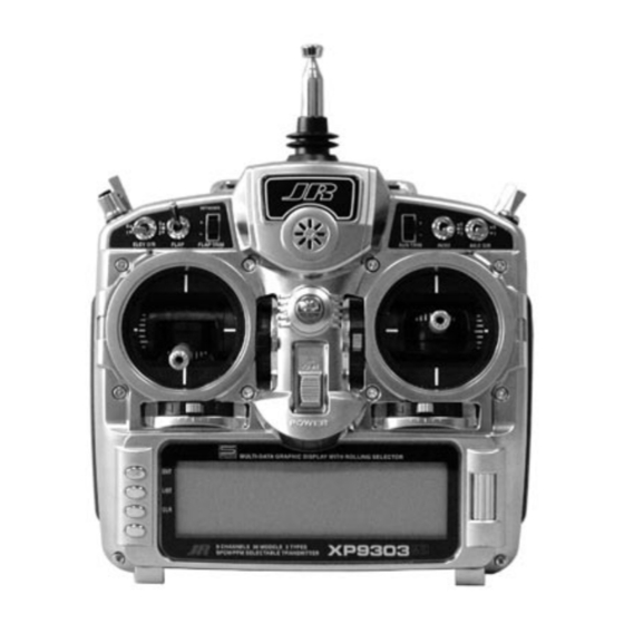
Page 9: Xp9303 Transmitter Features (Front
XP9303 Transmitter Features (Front) Mix Switch AUX2 Aileron Elevator AUX4/ Dual Rate Dual Rate Rudder Dual Aux Trim Gear Switch Rate Flap Trim Trainer Button Flap Switch Lever Lever Throttle/ Elevator/ Rudder Stick Aileron Stick Throttle Trim Elevator Trim Rudder Trim... -
Page 10: Xp9303 Transmitter Features (Rear
XP9303 Transmitter Features (Rear) Battery Cover CAUTION: THE BATTERY CONNECTION IS KEYED SO THAT IT CAN ONLY BE PLUGGED IN ONE DIRECTION. DO NOT FORCE... -
Page 11: Xp9303 Transmitter Features (Internal
XP9303 Transmitter Features (Internal) ELEVATOR TENSION SCREW RUDDER TENSION SCREW AILERON TENSION SCREW THROTTLE TENSION SCREW Control Stick Tension Adjustment Remove the six transmitter back screws as shown on the Adjust each screw for desired tension (counter-clockwise previous page. Remove the transmitter back, being careful to loosen stick feel;... -
Page 12: Advanced Digital Trims
Please also note that unlike conventional mechanical trim The XP9303’s Aileron, Elevator, Throttle and Rudder trim levers, when the XP9303 transmitter is in the off position, levers feature an audible center trim beep. This is helpful no changes can be made to the trim values during in determining the trim levers center position during transportation. -
Page 13: Direct Servo Control (Dsc)
Deluxe Switch Harness to use in the original setup of your aircraft while still – JRPA001, or a JR Chargeswitch – JRPA004, for the in the workshop. Because of the lower current draw on your transmitter, your working time at the bench will be DSC function to work.) Turn the switch harness to the... -
Page 14: Neckstrap Attachment
Neckstrap Attachment An eyelet is provided on the face of the XP9303 transmitter that allows you to connect a Neck Strap (JRPA023). This hook has been positioned so that your transmitter has the best possible balance when you use the neck strap. -
Page 15: Installation Requirements
4. Mount all switches away from the engine exhaust and correctly installed in your model. Here are a few away from any high vibration areas. Make sure the suggestions for installing your JR® equipment: switch operates freely and is able to operate over its full travel. -
Page 16: Introduction
READ INTRODUCTION For those who are comfortable with programming and The ACRO mode of the XP9303 system is intended for would like to dive right in with a minimum amount of powered fixed-wing aircraft. It contains a host of advanced... -
Page 17: Access The System Menu
ACCESS THE SYSTEM MENU 1. The System menu [SYSTEM M.] is obtained by holding down the ENT button while turning the transmitter on. [SYSTEM M.] INFO-DISP TRANSFER Model SEL TRIM STEP MDL Name Devic. SEL Type SEL Wing TYPE MDL Reset MODULAT. -
Page 18: Reset The Model
RESET THE MODEL When setting up a new model it is important to reset 1. In the SYSTEM Menu, highlight and select MDL all parameters to their default or factory settings Reset using the Selector. before proceeding with any other programming. This 2. -
Page 19: To Activate The Acro Mode
TO ACTIVATE THE ACRO MODE 1. In the SYSTEM Menu, highlight and select Type SEL After having selected and reset a model memory, it is time to tell the TX that the ACRO mode is to be used for this using the Selector. -
Page 20: Select A Modulation Type
SELECT A MODULATION TYPE 1. In the SYSTEM Menu, highlight and select The XP9303 system supports two types of modulation – SPCM and PPM (FM). The correct modulation type MODULAT. using the Selector. must be selected to match the receiver in the aircraft or 2. -
Page 21: Acro - System Menu - Advanced Functions
2nd throttle channel, complete with control some of the more advanced features of the independent trim and throttle curves to accommodate XP9303 system. They are the Devic. SEL and twin-engine aircraft. Wing Type functions. Each of the options in these two functions is described The Devic. -
Page 22: Flight Modes
Three Flight Modes are available in the XP9303 system. to do different things by flipping a single switch. When Flight Modes are activated, they are selected during... -
Page 23: To Activate Flight Modes
To Activate Flight Modes 1. From SYSTEM M. highlight and select Devic. SEL using the Selector. [Devic. SEL] FLIGHT MODE GEAR FLAP AUX2 AUX3 AUX4 GEAR FLAP AUX2 AUX3 RUDD LEV D/R TRIM OUT: INH 2. Using the Selector, highlight and select INH under Once one of the 3-position switches is selected, Flight FLIGHT MODE. -
Page 24: Trim:com (Flight Modes
Common or shared by the 3 Flight Modes. If FM may have a tendency to cause the aircraft trim to is selected, the XP9303 keeps track of the digital trims change, then select FM for the TRIM parameter. The... -
Page 25: Switch Assignments
SWITCH ASSIGNMENTS 1. From within the Devic.SEL function, use the Selector The XP9303 provides the ability to change the standard default switch assignments for GEAR, FLAP, AUX2, to highlight and select GEAR, FLAP, AUX2, AUX3, AUX3, and AUX4. Changing the assignments may be a or AUX4 along the top line of the display. -
Page 26: Activate/Inhibit Switches
ACTIVATE/INHIBIT SWITCHES The XP9303 provides the ability to inhibit or otherwise 1. If GEAR, FLAP, AUX2, AUX3, or AUX4 are to be disable a number of the levers and switches on the used as a 2nd primary flight control, then inhibit the transmitter –... -
Page 27: Wing Type
WING TYPE The Wing Type function provides for 3 different wing types The Wing Type function also provides for aircraft that (NORMAL, FLAPERON and DELTA). NORMAL wing type have a V-Tail configuration where the 2 Elevators are used is used when the Aileron channel is the only channel to be for both Elevator and Rudder control. -
Page 28: Wing Parameter - (Wing Type
WING Parameter – (Wing Type) 1. Highlight and select Wing TYPE in the SYSTEM parameter set to the default of NORMAL and plug the Menu using the Selector. Aileron servo into the Aileron channel (Ch2) of the RX. Also use NORMAL if the aircraft has flaps that are 2. -
Page 29: V-Tail (Wing Type
V-tail (Wing Type) 1. If the aircraft has a V-tail configuration, highlight INH the Selector toggles the parameter between ACT and next to V-tail in the Wing TYPE function and press the INH. If the aircraft has a normal tail, make sure INH Selector until ACT appears. -
Page 30: Twin E. (Wing Type
Twin E. (Wing Type) If the aircraft is equipped with twin engines, the Twin 1. Highlight and select INH next to Mate under Twin Engine feature (Twin E.) may be used for a 2nd throttle E. A list of available channels will appear. Select the channel with an optional separate digital trim. -
Page 31: Trim Step
The Trim Step function provides for adjusting the Use a fairly coarse setting such as 4–6 when test flying sensitivity of the XP9303 trim levers and switches. It is an aircraft in order to be able to trim the aircraft quickly, useful during and after initial trimming of the aircraft, in and then use a finer setting such as 3–1 for final... -
Page 32: Acro - Function List
ACRO – FUNCTION LIST Once the basic aircraft configuration has been defined in The descriptions are general in nature and are intended to the SYSTEM Menu, the functions found in the Function provide enough information to decide whether or not to List [FUNC.LIST] are used to complete the setup and use a function and what types of selections and settings then to adjust how the aircraft flies. -
Page 33: Sub Trim
SUB TRIM Sub Trims are intended for relatively minor adjustments Use Sub Trims to fine-tune the alignment of servo arms. to servo linkages and not for major trim adjustments to Install servo arms on the servos so that the arms are at the aircraft. -
Page 34: Trvl Adj. - Travel Adjust
TRVL ADJ. – TRAVEL ADJUST Travel Adjust, sometimes referred to as ATV, is used to 1. Highlight and select TRVL ADJ. in the FUNC.LIST to adjust how far a servo travels in each direction. After the obtain the Travel Adjust display. linkages have been installed and attached to the servos, 2. -
Page 35: D/R & Exp - Dual Rate And Exponential
D/R & EXP – DUAL RATE AND EXPONENTIAL Dual Rates and Exponential curves can be very effective maneuver is to be performed and the response that is in setting up an aircraft to have a particular “feel” when desired from the aircraft. For an in-depth description of D/R and Exponential, please refer to the Dual Rates and performing different types of maneuvers. -
Page 36: Thro Curv - Throttle Curve
THRO CURV – THROTTLE CURVE An ideal throttle setup is linear in nature where ¼ THRO CURV can also be used to set up a special throttle stick results in ¼ RPM, ½ stick results in ½ RPM, etc. response where the engine quickly comes up to a certain However, many of today’s gas engines employ pumping RPM and then advances very slowly to provide precise carburetors which do not produce a very linear response. - Page 37 THRO CURV – THROTTLE CURVE (continued) Note: If Twin E. has been activated for a twin engine However, instead of being named Pos0 & Pos1, aircraft, there will be a Pos0 and Pos1 for both the they are named RTH.0, RTH.1, LTH.0, and LTH.1. right and left engines, providing a total of 4 possible They represent Right Throttle Pos0 &...
-
Page 38: Flap Sys. - Flap System
Delay in .1 second increments up to 2 seconds maximum. The Delay determines how long it takes for the Flaps and Elevator to reach their positions. The XP9303 insures that the Flaps and Elevator reach their positions at the same... -
Page 39: Auto Land (Flap System
AUTO LAND (Flap System) The Auto Land feature automatically retracts the Flaps and Elevator compensation when the throttle is raised above a specified throttle position. [FLAP SYS.] N NORM FM0: SW FLAP SW ELEV FM1: SW Land FM2: SW NORM U100% AUTO LAND FLAP Mid... -
Page 40: Elev - Elevator Compensation (Flap System
ELEV – ELEVATOR COMPENSATION (Flap System) The ELEV values represent the Elevator deflection that 2. Scroll to the Mid parameter beside ELEV and select it. will occur when the Flaps are deployed to their various Set the value either U (up) or D (down) to introduce up positions. -
Page 41: Flap - (Flap System
FLAP – (Flap System) The FLAP values represent how far the flaps deflect when 1. Put the Flap switch in its uppermost (Normal) position in the NORM, Mid, and Land positions. The NORM (no flaps deployed). Scroll to the NORM parameter position represents normal flying where the flaps are fully next to FLAP on the display. -
Page 42: Fm0-Fm2 (Flap System
FM0-FM2 (Flap System) If Flight Modes have been activated in the Devic. SEL function of the SYSTEM Menu then FM0, FM1 and FM2 will appear along the right side of the Flap System display to represent the 3 Flight Modes. Each of the Flight Modes can be assigned one of the Flap values (NORM, Mid, or Land), so when that Flight Mode is selected during flight, the Flaps deploy to that position. -
Page 43: Delay (Flap System
Elevator to reach their positions. The display using the Selector. Then use the rotary to XP9303 automatically times the Flaps and Elevator so select a delay between .1 second and 2.0 seconds. that they reach their positions at the same time, resulting in very smooth Flap deployment and retraction. -
Page 44: EleFlp M - Elevator-To-Flap Mising
FLP M – ELEVATOR-TO-FLAP MIXING The XP9303 features a built-in mixer for Elevator-to- with Elevator input can be changed by using positive and Flap. The mixer causes the Flaps (or Flaperons) to move negative values. when the Elevator is moved, resulting in tighter looping... -
Page 45: AilRud M - Aileron-To-Rudder Mixing
RUD M – AILERON-TO-RUDDER MIXING The XP9303 also features a built-in mixer for Aileron- be made to move in either direction by using positive or to-Rudder. The mixer causes the Rudder to deflect when negative values. the Ailerons are moved resulting in coordinated turns. -
Page 46: Ail Diff. - Aileron Differential
(negative differential). Test fly the aircraft and return to this function to make adjustments until the The XP9303 provides an Aileron Differential function that yaw tendency has been eliminated. That is all that is allows adjustment of the Aileron that deflects downward... - Page 47 AIL DIFF. – AILERON DIFFERENTIAL (continued) 2. At this point, it is assumed that there are to be 2 differential off is desired. Highlight and select Pos1 Aileron differential values. If one of these values is and set the percentage of differential. A positive value set to zero, Aileron differential can be turned off by causes the downward Aileron to travel less, while a selecting the position that has the 0 values.
-
Page 48: Srv. Speed - Servo Speed
SRV. SPEED – SERVO SPEED The XP9303 system provides the ability to adjust the Servo speed can also be useful on the throttle channel. speed of servos on each channel in both directions. The The throttle servo can be slowed down such that the... -
Page 49: Snap Roll
SNAP ROLL The XP9303 has a Snap Roll system that is comprised of If the Snap Roll function is to be used, highlight and a Snap Roll switch that is used in conjunction with Flight select Snap Roll in the FUNC.LIST and then select INH Modes to select a direction (Right/Up, Right/Down, Left/ to activate it. -
Page 50: Gyro Sys. - Gyro System
GYRO SYS. – GYRO SYSTEM The XP9303 features a very sophisticated Gyro Gain Up to 2 gyros may be used to control two of the three Sensitivity System that allows in-flight selection of 3 gyro primary flight controls (Elevator, Rudder, or Aileron). -
Page 51: Fixed Gyro Gain (Gyro System
FIXED GYRO GAIN (Gyro System) Fixed Gyro Gain does not use the Stick Override Gain 2. Decide on which switch to use to control gyro gain. feature. Whichever of the 3 gains is presently selected The Flap switch and the AUX2 switch are the only 3- remains in effect and moving the control stick does not position switches that can be used by the Gyro System. -
Page 52: Stick Override Gyro Gain (Gyro System
STICK OVERRIDE GYRO GAIN (Gyro System) Stick Override Gyro Gain is very popular with aerobatic Stick Override Gyro Gain is identical to Fixed Gyro Gain pilots, as it allows the pilot to instantaneously override in all regards except that the control stick(s) progressively the gyro by moving the stick. -
Page 53: Prog Mix - Programmable Mixers
PROG MIX – PROGRAMMABLE MIXERS The XP9303 System provides 4 Standard programmable • Eliminate Roll-Coupling where the aircraft rolls mixers (PROG.MIX3 - PROG.MIX6) and 2 Multi-Point when there is Rudder input. The mixer causes the programmable mixers (PROG.MIX1 & PROG.MIX2). -
Page 54: Standard Programmable Mixer - Example: Down Elevator At Idle
STANDARD PROGRAMMABLE MIXER – Example: DOWN ELEVATOR AT IDLE Perhaps the best way to describe a Programmable The Mix parameters will be selected and set in the Mixer is by example. The example below demonstrates following order: Program Mix number, Master, Slave, a program mix for an aircraft that pulls-out or pitches Switch, Travel/Direction, and Offset. - Page 55 STD PROGRAMMABLE MIXER – Ex: DOWN ELEV AT IDLE (continued) The Elevator should barely move downward when the 8. Verify Operation. Highlight and select the position throttle is set to idle. If the Elevator moves upward, containing the +3% value using the Selector, move change the +3% to a –3% to reverse the direction that the Gear switch to the ON position, and move the the Elevator travels.
-
Page 56: Multi-Point Mixer - Example: Eliminate Pitch-Coupling
MULTI-POINT MIXER – Example: ELIMINATE PITCH-COUPLING The example below demonstrates a Multi-Point Program The Mix parameters will be selected and set in the Mix for aircraft that pitch towards the landing gear when following order: Program Mix number, Master, Slave, holding Rudder for knife-edge flight –... - Page 57 MULTI-POINT MIXER – Ex: ELIMINATE PITCH-COUPLING (continued) 5. Set Points for Travel and Direction. There are 7 Point-0 points along the travel of the Rudder (the line that is - 10% (At full Right Rudder the Elevator will deflect intersected by the vertical line that moves right and Up 10%) left with the Rudder stick).
-
Page 58: Fail Safe
FAIL SAFE Fail Safe is available only when SPCM has been More often than not, the pilot will not realize the selected as the Modulation Type in the SYSTEM system went into Fail Safe except for hearing the Menu. The receiver must be of the PCM variety, as Fail throttle momentarily reduce RPM. -
Page 59: Trainer - Trainer System
XP9303 USED AS MASTER (INSTRUCTOR) – (Trainer System) 1. If the XP9303 is being used as the Master TX (the TX operated by the instructor), select the channel(s) that are to be operated by the Slave TX (TX operated by the student) when the trainer switch is depressed. -
Page 60: Xp9303 Used As Slave (Student) - (Trainer System
XP9303 USED AS SLAVE (STUDENT) – (Trainer System) 1. If the XP9303 is to be used as the Slave TX (TX used by the student), be sure that the currently selected model is set to PPM Modulation (see MODULAT in the SYSTEM Menu if the Slave TX is a XP9303). -
Page 61: Timer - Timer System
TIMER – TIMER SYSTEM The XP9303 contains a Timer System that contains two 1. To configure the timer as a Countdown timer highlight timers. One is an integrated timer that keeps track of and select Timer in the FUNC.LIST to obtain the total time that the TX has been on for the model and Timer display. -
Page 62: Monitor
MONITOR The Monitor function displays each channel and shows 1. To access the Monitor function, highlight and the movement of channels when sticks, levers and select MONITOR in the FUNC.LIST to obtain switches are moved. It renames channels according the Monitor display. to special assignments to assist in identifying what is moving. -
Page 63: Utility Functions
UTILITY FUNCTIONS The XP9303 System includes two utility functions to help in the SYSTEM Menu. The Copy function is actually with managing the settings that have been programmed part of the Model SEL function while the TRANSFER into the XP9303 model memories. These functions function has its own set of displays. - Page 64 COPY – COPY CURRENT MODEL (continued) The display shows the currently selected model on top To change the lower model memory that is to with a down-arrow pointing to the lower model memory receive the copy of the current model, highlight and that the current model will be copied into.
-
Page 65: Transfer - Transfer The Model To Another Transmitter Or To Datasafe
RECEIVE A MODEL INTO THE XP9303 – (Transfer function) 1. Hold the ENT button while plugging the DSC cord into Plug the other end of the DSC cord into another XP9303 the back of the transmitter to obtain the transmitter while holding the ENT button down and SYSTEM Menu. - Page 66 Press start on the transmitting XP9303 or 4. Select the model memory that is to receive the data by DataSafe unit to begin the data transfer to the XP9303. highlighting and selecting the model name/memory number and then scrolling to and selecting the model memory that is to receive the data.
-
Page 67: Sub Trim Usage And Mechanical Advantage
SUB TRIM USAGE AND MECHANICAL ADVANTAGE SUB TRIM Sub Trims are intended for relatively minor adjustments The diagram below illustrates an ideal servo/linkage setup to servo linkages and not for major trim adjustments to when the servo is at neutral (no sub trim and digital trims the aircraft. -
Page 68: Dual Rates And Exponential Curves
DUAL RATES AND EXPONENTIAL CURVES Dual Rates and Exponential curves can be very effective When using Exponential, a positive (+) exponential in setting up an aircraft to “feel” the way you would like percentage causes the servo to move less when the stick it to feel when performing different types of maneuvers. -
Page 69: Servo Precautions
Overloading or stalling a servo can • Ensure the servo horn is securely fastened cause excessive current drain. to the servo. Use only the JR® servo arm screws provided; the size is different from other • Make sure all servos move freely through their manufacturers. -
Page 70: Federal Aviation Administration
Federal Aviation Administration 1. Purpose b. Select an operating site at sufficient distance from populated areas so you do not create a This advisory outlines safety standards for operations of noise problem or a potential hazard. model aircraft. We encourage voluntary compliance with these standards. -
Page 71: Frequency Chart
FCC rules. The Federal Communications Commission (FCC) requires that changes in transmitter frequency must be performed Channels 12–14 are not available through JR®. only by an authorized service technician (Horizon Service Center). -
Page 72: Warranty Information
Repair Service Directions Mail your system to: In the event that your JR radio needs service, please Horizon Service Center follow the instructions listed below. 4105 Fieldstone Road 1. -
Page 73: Setup Sheet (Aircraft
Setup Sheet (Aircraft) MODEL NO MODEL NAME SPOI AIL1 ELEV RUDD AIL2 FLAP AUX2 AUX3 NORM NORM NORM NORM NORM NORM NORM NORM REVERSE SW SUB TRIM TRAVEL ADJUST FAIL SAFE (SPCM) AILE ELEV RUDD AUTO RUDD D/R ACT INH DOWN ELEV FLAP... - Page 74 © 2004, Horizon Hobby, Inc. 4105 Fieldstone Road Champaign, IL 61822 (877) 504.0233 www.horizonhobby.com A7011...
Need help?
Do you have a question about the XP9303 and is the answer not in the manual?
Questions and answers