Table of Contents
Advertisement
Quick Links
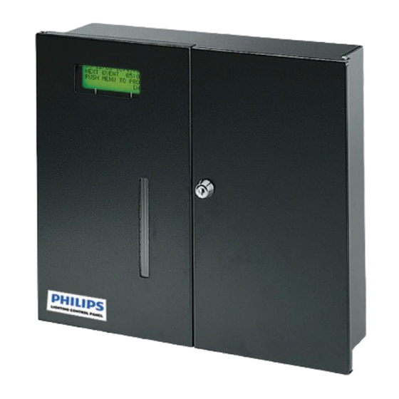
LRC2410
8X20A Relay Control Panel
BACnet MS/TP Enabled
INSTALLATION INSTRUCTIONS
READ AND FOLLOW ALL SAFETY INSTRUCTIONS!
SAVE THESE INSTRUCTIONS AND DELIVER TO OWNER AFTER INSTALLATION
WARNING
!
To reduce the risk of death, injury or property damage from fire, electric shock, cuts,
abrasions, falling parts, and other hazards:
•
Service of the equipment must be performed by qualified service personnel.
•
Installation and maintenance must be performed by a person familiar with the construction
and operation of this product and any hazards involved. All applicable codes and ordinances
must be followed.
•
Read this document before installing, servicing, or maintaining this equipment. These
instructions do not cover all installation, service, and maintenance situations. If your situation
is not covered, or if you do not understand these instructions or additional information is
required, contact
WARNING
!
Before installing, servicing, or maintaining this equipment, follow these general precautions.
To reduce the risk of electrocution:
•
Make sure the equipment is properly grounded.
•
Always de-energize any equipment before connecting to, disconnecting from, or
servicing the equipment.
To reduce the risk of fire:
•
Use supply conductors with a minimum installation temperature rating as specified.
To reduce the risk of personal injury from cuts, abrasions:
•
Wear gloves to prevent cuts or abrasions from sharp edges when removing from
carton, handling and maintaining this equipment.
•
Do not install a damaged equipment.
IMPORTANT SAFETY INSTRUCTIONS
Philips Lighting Controls.
LRC2410 Installation Instructions, Part No. CDCS000314 Rev. A 7/11
Page 1
Advertisement
Table of Contents

Related Manuals for Philips LRC2410


Summary of Contents for Philips LRC2410
-
Page 1: Installation Instructions
To reduce the risk of personal injury from cuts, abrasions: • Wear gloves to prevent cuts or abrasions from sharp edges when removing from carton, handling and maintaining this equipment. • Do not install a damaged equipment. LRC2410 Installation Instructions, Part No. CDCS000314 Rev. A 7/11 Page 1... -
Page 2: Before You Start
Remove ALL metal shavings and excess contaminants Semi-recessed mounting option: from the enclosure before applying power to the Opening should be 14 5/8" wide, 14 1/16" high, and requires cabinet. 3 3/8" wall depth minimum. LRC2410 Installation Instructions, Part No. CDCS000314 Rev. A 7/11 Page 2... - Page 3 120 or 277 VAC, 60 Hertz. AWG or (2) #12, #14 AWG maximum. DO NOT connect 2 pole circuits or loads to LRC2410 The power supply terminal block label shows the connection positions for each voltage, see Figure 3...
- Page 4 COIL 3 & 4 NEUTRAL 2 POLE LINE LOAD LOAD COIL LINE (RED) 2 POLE CIRCUIT BREAKER 30 AMP, 600V MAX Figure 5 - Load Connections, 4 Single Pole, 2 Double Pole LRC2410 Installation Instructions, Part No. CDCS000314 Rev. A 7/11 Page 4...
- Page 5 COIL LINE (BLUE) LINE LOAD FACTORY WIRING CONTRACTOR LINE LOAD SUPPLIED WIRING COIL NEUTRAL (WHITE) LINE LOAD LINE LOAD COIL LINE (RED) Figure 6 - Load Connections, 4 Double Pole LRC2410 Installation Instructions, Part No. CDCS000314 Rev. A 7/11 Page 5...
- Page 6 (TYPICAL) XFMR B POWER NET IN NET OUT 20 VDC +20V GND 0.5A ACCESSORY SHLD SHLD POWER OUTPUT ON/OFF NETWORK OVERRIDE IN/OUT CONTACT Figure 7 - Low Voltage Connections LRC2410 Installation Instructions, Part No. CDCS000314 Rev. A 7/11 Page 6...
- Page 7 - End units must be terminated. Units in the middle of the network are not terminated. - LRC2410 MS/TP Network wiring connections use IN and OUT terminal blocks. There is no need to connect the IN and OUT network wire in the same terminal block. See Figure 8 for details.
- Page 8 OPEN BRAIN BOARD RIBBON CABLE TERMINATE TERMINATION BIAS JUMPERS TERMINATE BATT BIAS RESET TERMINATE BIAS MSTP NETWORK Figure 9 - MS/TP NETWORK TERMINATION JUMPERS TERMINATION JUMPER SETTINGS LRC2410 Installation Instructions, Part No. CDCS000314 Rev. A 7/11 Page 8 RS232 KEYPAD/LEDS...
-
Page 9: Troubleshooting Procedures
SYMPTOM: THE INPUT BUTTON(S) ARE OPERATING THE WRONG RELAY(S) Check Programming. The RELAY BUTTON LED for each relay controlled by an INPUT BUTTON will light when switched on by the input. If a programming error is suspected, consult the LRC2410 Operation and Maintenance Manual for detailed programming information. - Page 10 LRC2410 Installation Instructions, Rev. A May 2011 © 2011 All rights reserved. Reproduction in whole or in part is prohibited without the prior written consent of the copyright owner. The information presented in this document does not form part of any quotation or contract, is believed to be accurate and reliable and may be changed without notice.
Need help?
Do you have a question about the LRC2410 and is the answer not in the manual?
Questions and answers