Table of Contents
Advertisement
Quick Links
Advertisement
Table of Contents

Subscribe to Our Youtube Channel
Related Manuals for Philips Antumbra


Summary of Contents for Philips Antumbra
-
Page 1: Antumbra
Antumbra Installation Guide Revision 02... - Page 2 13 October, 2017 Antumbra Product Overview...
-
Page 3: Table Of Contents
Installation Procedure 2.2.1 Base Unit Installation 2.2.2 Antumbra shielding 2.2.3 Button Installation (AntumbraButton) 21 2.2.4 Button Installation (AntumbraDisplay) 22 2.2.5 Fascia Installation (AntumbraTouch) 23 Ordering Antumbra Panels AntumbraButton 3.1.1 Spare Parts AntumbraDisplay 3.2.1 Spare Parts AntumbraTouch 3.3.1 Spare Parts Antumbra... -
Page 4: About This Guide
13 October, 2017 About this Guide Guide Overview This guide is designed to assist in the ordering and installation of the Antumbra Panel user interface. A working knowledge of Dynalite commissioning processes is required to effectively use this document. For more information on commissioning processes, consult the Antumbra Commissioning Guide. -
Page 5: Product Overview
13 October, 2017 Product Overview The Philips Dynalite Antumbra Panel series is a unique and stylish range of user interfaces, combining contemporary design with superior functionality to enable intuitive control of lighting, HVAC and other connected devices and systems. The Antumbra Panel series is one of the most flexible user interface solutions available in the market. -
Page 6: Application Module
The Application Module consists of the buttons, rim, base unit and mounting plate. The buttons/touch panel and rims of each Antumbra unit come in different colours and finishes. The rim has built-in ventilation to increase the responsiveness of the temperature sensor. -
Page 7: Antumbrabutton
To complement these button finishes, rim finishes are available in white, magnesium, chrome and brushed aluminium, providing a wide range of décor matching possibilities. Custom labelling of icons and engraved text is available for each panel. 1.3.1 Product Architecture Antumbra Product Overview... -
Page 8: Hardware Dimensions (Eu)
13 October, 2017 1.3.2 Hardware Dimensions (EU) 1.3.3 Hardware Dimensions (NA) Antumbra Product Overview... -
Page 9: Base Unit
When attaching the rim, ensure that the holes on the rim are positioned over the temperature sensor. Note: To remove the buttons from the panel, lift the button edge on the left and right side of the panel before lifting the button at the center. Antumbra Product Overview... -
Page 10: Antumbradisplay
Safety Extra-Low Voltage (SELV) device. This panel is available in white, silver, magnesium and brushed aluminium button finishes. Complementary rim finishes are available in white, magnesium, chrome and brushed aluminium, providing a wide range of décor matching possibilities. 1.4.1 Product Architecture Antumbra Product Overview... -
Page 11: Hardware Dimensions (Eu)
13 October, 2017 1.4.2 Hardware Dimensions (EU) 1.4.3 Hardware Dimensions (NA) Antumbra Product Overview... -
Page 12: Base Unit
When attaching the rim, ensure that the holes on the rim are positioned over the temperature sensor. Note: To remove the buttons from the panel, lift the button from the left and/or right edge of the panel before lifting the button at the center. Antumbra Product Overview... -
Page 13: Antumbratouch
The base unit contains the panel’s sensor devices, buzzer and LEDs. It includes the proximity sensor, the daylight sensor and the temperature sensor. The LEDs are used to provide backlight to the buttons, and to create the lightwash effect around the panel. Antumbra Product Overview... -
Page 14: Hardware Dimensions (Eu)
13 October, 2017 1.5.2 Hardware Dimensions (EU) 1.5.3 Hardware Dimensions (NA) Antumbra Product Overview... -
Page 15: Antumbratouch Base Unit
The panel can be mounted in both portrait and landscape orientations. Ensure the holes on the rim are positioned over the temperature sensor to allow airflow. The arrows indicate the side that has to be at the top when the panel is mounted. Antumbra Installation... -
Page 16: Installation
DyNet Network DyNet RS485 3 Twisted Pair & Overall Screen Unplug the five way screw socket on the back of the Communication module. Terminate the network cable following the diagram below. All devices must be terminated correctly as shown. Antumbra Installation... -
Page 17: Installation Procedure
Antumbra panels are powered from the DyNet network, which is classified as SELV/Class II (for NA) Overvoltage category III in accordance with IEC60664-1(0.8 kV surge). Ensure that installation of the Antumbra Panel is in compliance with HD 60364 - 4I where applicable. - Page 18 3. The plate’s orientation can be either way. Using the long mounting screws provided, fix the mounting bracket to the wall. Installers must use the screws provided as different screws could damage the panel once fully installed. 4. Ensure that the mounting plate is level and adjust if required. Antumbra Installation...
- Page 19 6. Push the panel assembly into the mounting bracket. Locate and fix the application unit to the mounting bracket using the two smaller screws through the mounting holes. Recheck the level of the panel and adjust if required Antumbra Installation...
-
Page 20: Antumbra Shielding
13 October, 2017 2.2.2 Antumbra shielding False triggering of the proximity sensor may occur if the shield terminal is not connected to the wall box or metal mounting plate. False triggering of the Proximity Sensor can be prevented by ensuring the following points are considered during installation: •... -
Page 21: Button Installation (Antumbrabutton)
Once correctly attached, enabled buttons will have a smooth tactile click when pressed. If any enabled button does not have a positive click when pressed, check for obstructions or the disable switch being set incorrectly. Antumbra Installation... -
Page 22: Button Installation (Antumbradisplay)
To attach the small buttons, ensure that the raised ridge on each button is aligned with the corresponding space between the application module and the rim. Press down on the top and bottom of the button until it clicks into place. Once correctly attached, each button will have a smooth tactile click when pressed. Antumbra Installation... -
Page 23: Fascia Installation (Antumbratouch)
To remove the glass face from the application base, loosen the glass face from the bottom and then the sides and later lift it from the application base. The pictures below show the correct way of removing the glass face from the application base. Antumbra Ordering Antumbra Panels... -
Page 24: Ordering Antumbra Panels
13 October, 2017 Ordering Antumbra Panels The Antumbra panel is split into two parts, the Application module and the Communication module. These two units are ordered separately. Both of these units are required for a complete installation. The Application module is available in multiple button and rim finishes, as detailed throughout this chapter. -
Page 25: Spare Parts
Spare - Button Application Module Kit PABSA-AMK Spare - Antumbra Mounting Grid PABSE-GRID Spare - Antumbra Mounting Grid PABSA-GRID Spare - Antumbra Mounting Screws Kit PABSE-SCREWS Spare - Antumbra Mounting Screws Kit PABSA-SCREWS Sales Demo Kit - BUTTON PABSE-DEMOPACK Sales Demo Kit - BUTTON... -
Page 26: Antumbradisplay
13 October, 2017 AntumbraDisplay This part number describes a European style AntumbraDisplay panel with magnesium buttons, chrome rim and no button labelling. Antumbra Ordering Antumbra Panels... -
Page 27: Spare Parts
Spare - Display Button Magnesium PADSA-MX Spare - Display Button Aluminum PADSA-AX Spare - Display Rim White PADSE-XW Spare - Display Rim Aluminum PADSE-XA Spare - Display Rim Chrome PADSE-XC Spare - Display Rim Magnesium PADSE-XM Antumbra Ordering Antumbra Panels... -
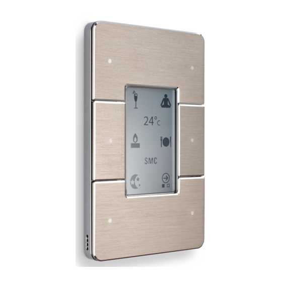
Page 28: Antumbratouch
13 October, 2017 AntumbraTouch This part number describes an Australian/American AntumbraTouch panel with white buttons, white rim and labelled buttons. Antumbra Ordering Antumbra Panels... -
Page 29: Spare Parts
Black PATSA-BB-X Spare - Touch Glass Assembly Black Black PATSA-BB-L Spare - Touch App Module Kit PATSE-AMK Spare - Touch App Module Kit PATSA-AMK Sales Demo Kit - TOUCH PATSE-DEMOPACK Sales Demo Kit - TOUCH PATSA-DEMOPACK Antumbra Ordering Antumbra Panels... - Page 30 13 October, 2017 Antumbra Ordering Antumbra Panels...
- Page 31 JOSEPH JOUKHADAR sels@automated.net.au +61 2 9247 0731 Suite 4, Level 5 37 Pitt Street Sydney NSW 2000 © 2017 Koninklijke Philips Electronics N.V. All rights reserved. Philips International B.V. The Netherlands Document Revision: 01...
Need help?
Do you have a question about the Antumbra and is the answer not in the manual?
Questions and answers