Philips RC9800i Service Manual
Hide thumbs
Also See for RC9800i:
- User manual (62 pages) ,
- Quick start manual (7 pages) ,
- Specification sheet (3 pages)

Related Manuals for Philips RC9800i


Summary of Contents for Philips RC9800i
- Page 2 RC9800i /00/05/17 DS9800i Service Manual TABLE OF CONTENTS Page Specifications & Warning ............Mechanical Instructions ............. Electrical diagrams ..............Mainboard component layout ........... Exploded view & Mechanical Parts list ........Electrical Parts list ..............Mechanical Instructions - Docking station .........
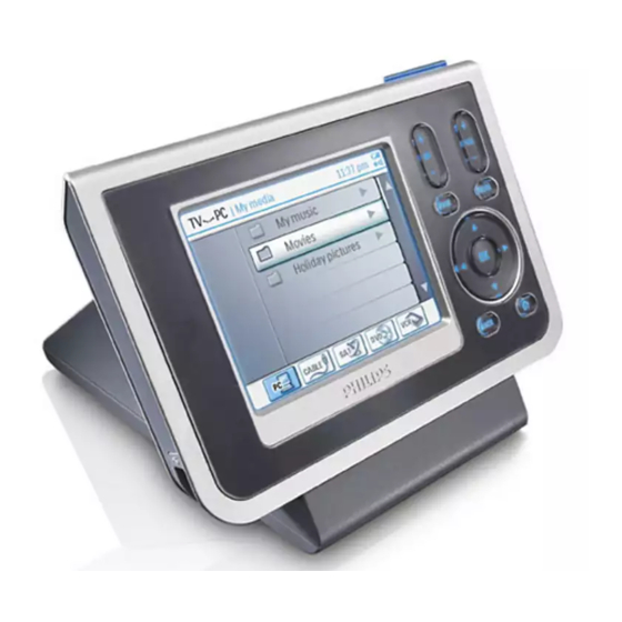
- Page 3 : RC5, RC6, and learnable format : 950nm ± 50nm. Infrared wavelength: PRODUCT DESCRIPTION RC9800i is a touchscreen LCD remote control with the following key characteristics: Colour active matrix touchscreen TFT LCD with white LED backlight (320x240, 16bit color) Backlight brightness control...
- Page 4 MECHANICAL INSTRUCTIONS Set Disassembly 1. Remove 2 x screw (Torx screw M2x6) see picture - arrows Side C Side B Side A 2. Put a sharp knife between toppart and bottompart and use this as lever to separate the two parts. see picture Side A Side B Side C...
- Page 5 MECHANICAL INSTRUCTIONS Disassembly LCD & Buttons Fig. 2 1. Remove 5 x screw (Torx screw M2x5 ). see fig.1 - arrows 2. Remove speaker cable see fig.1 - arrow C 3. Fig.2 arrow B: Release flex cable lock in direction arrow C and remove flex 4.
- Page 6 MECHANICAL INSTRUCTIONS Set Reassembly 1. Put LCD support frame (*item17) and LCD (*item 16) together. 1. Put LCD support assy (*item16 ,17) in the Toppart assy (*item1) and mount the 4 screws (Torx screw M2x4) back. see arrows 2. Place Keymat assy (*item 9). 3.
- Page 7 MECHANICAL INSTRUCTIONS Set Reassembly Fig. 2 Fig. 1 7. Place mainboard assy. (*item1001) 8. Mount the 5 screws (Torx screw M2x5) back. see arrows 9. Connect speaker cable. see arrow C 10.Connect the two flex cable to the connectors and close the cable locks. see fig.2 arrows A -B 11.
- Page 8 F122 F123 SPI2_MOSI 3126 F7 F113 3127 F2 SPI2_nSS 3128 F2 F114 SPI2_EXT_IRQ 3129 D3 USED FOR PHILIPS WIFI CHIPSET F115 3130 D3 SPI2_SCLK 3131 C2 3132-1 B6 3132-2 B7 3132-3 D6 3132-4 D7 3104 207 5038 3133-1 E10 bl130-1 dd 13-07-04...
- Page 9 ELECTRICAL DIAGRAM 1201 D17 1701 D14 1702 C15 2201 I3 Memory-WIFI (CF) 2202 I3 2203 I3 2204 I4 2205 I4 2206 I4 2207 I4 2208 I5 2209 I5 2210 I5 JTAG{nTRST,TDI,TCK,TMS,nTDO_CPLD,nTDO_CPU} 2211 I6 VD_3V2 2212 I6 D(0:31) 2213 I7 2214 I7 VD_3V2_WIFI A(0:15) 2215 I7...
- Page 10 ELECTRICAL DIAGRAM G1 F9 1301 E12 1303 H10 1304 H14 Audio-USB-Tilt SW 1305 C10 2301 D10 2302 I13 2303 J6 2304 J6 2305 J6 2306 D10 2307 E11 2308 F11 2310 D7 2311 H13 2312 H9 2329 H5 2330 H6 2331 C7 2332 C8 VD_3V2...
- Page 11 ELECTRICAL DIAGRAM G2 J4 G3 J4 V1 G5 V2 G3 IR-Keypad 1401 D15 1402 E15 1403 D13 1404 D14 1405 D14 1406 D13 1407 D14 1408 D14 1409 D13 1410 D14 1411 D14 1412 E13 1413 E14 1451 C7 2401 C5 2402 C9 2404 H6 2405 H9...
- Page 12 ELECTRICAL DIAGRAM V3 J5 6521 B4 1502 F2 6522 D4 1523-1 D2 6523 D8 1523-2 C2 7501 D6 Power Charger-Reset-Key-Backlight 1525 G4 7502 F8 2501 H6 7503 F7 2502 G6 7504 E5 2503 B12 7506 K4 2504 B16 7507 B13 VD_3V2 VD_3V2 2505 C15...
- Page 13 ELECTRICAL DIAGRAM G4 H3 1601 I16 1602 B16 1604 C14 LCD-TS 1605 C15 1606 C15 1607 C16 1608 C16 2607 E12 2616 H4 2617 G6 2618 H6 2619 B8 2620 B8 2621 D6 TS{X-,X+,Y-,Y+} 2622 G5 1602 2623 I15 6607 6608 VD_3V2 2624 J13...
- Page 14 COMPONENT LAYOUT MAINBOARD COMPONENT LAYOUT SIDE-B VIEW COMPONENT LAYOUT SIDE-A VIEW 3104 207 5038 bl 132-1 dd 13-07-04 3104 207 5038 bl 132-2 dd 13-07-04...
- Page 15 3140 118 33800 AC/DC Adaptor AY3192/00 only for /00 3104 200 52360 Coax cable 3140 118 33810 AC/DC Adaptor AY3192/05 only for /05 For more information: 3104 200 05350 Factory Label 3140 118 33820 AC/DC Adaptor AY3192/17 only for /17 E-mail: erik.gybels@philips.com...
- Page 16 ELECTRICAL PARTS LIST MISCELLANEOUS CAPACITORS 1101 242254300937 RES XTL SM 32K76 12P5 2216 223891619849 CER2 0603 Y5V 25V 100N 1002 272217100128 WMOD WIFIB SIP WM-B-AG-02 2217 223891619849 CER2 0603 Y5V 25V 100N 1201 242202518586 CON V 60P F 0.50 SM 2218 223891619849 CER2 0603 Y5V 25V 100N...
- Page 17 ELECTRICAL PARTS LIST CAPACITORS RESISTORS 2506 223878615649 CER2 0603 X7R 16V 100N 3118 235003410339 RST NETW SM ARC24 4X 33R 2507 223891619849 CER2 0603 Y5V 25V 100N 3119 232270260339 RST SM 0603 RC21 33R 3120 235003410339 RST NETW SM ARC24 4X 33R 2508 202055296835 CER2 1210 X5R 6V3 22U...
- Page 18 ELECTRICAL PARTS LIST RESISTORS RESISTORS 3509 232270461604 RST SM 0603 RC22H 160K 1% 3231 232270260103 RST SM 0603 RC21 10K 3510 232270260104 RST SM 0603 RC21 100K 3238 232270260829 RST SM 0603 RC21 82R 3511 232270462005 RST SM 0603 RC22H 2M 1% 3239 232270260103 RST SM 0603 RC21 10K...
- Page 19 RST SM 0603 JUMP 7201 932218203668 IC SM MT48LC8M16A2TG-75 7202 932218203668 IC SM MT48LC8M16A2TG-75 FILTERS 7203 310420857412 RC9800i SW Assy CPLD 7205 310420857354 RC9800i SW Assy Doc 5104 242254945333 IND 1206 EMI 100MHZ 120R 5105 242254942979 IND 0603 EMI 100MHZ 60R...
- Page 20 ELECTRICAL PARTS LIST TRANSISTORS & IC’s 7401 310420883821 IC- SM M37540M4-090FP 7403 935262755125 IC SM 74AHC1G08GW 7405 933589760215 TRA SIG SM BC857B 7406 933957530668 IC SM LM393D 7408 933589760215 TRA SIG SM BC857B 7409 933589590215 TRA SIG SM BC847B 7410 933589590215 TRA SIG SM BC847B 7411...
- Page 21 DOCKING STATION DS9800i...
- Page 22 MECHANICAL INSTRUCTIONS Set Disassembly - Docking station 1. Remove the four rubber feet 2. Remove 4 x screw see arrows 3. Put the thumb in the middle from toppart 1 (see picture), press hardly downwards until the side slightly sag and put a sharp knife between toppart and bottom part and use this as lever to separate the two parts.
- Page 23 ELECTRICAL DIAGRAM PWB - 1 PWB-1 1102 HEC3600-016110 DC_GND 1101 DC_+ 1103 DAC_LO_IRQ LINEOUT_R LINEOUT_L HSJ1637-010510 A_GND 3104 207 5041 HLW13S-2C7 bl 130-1 dd 12-07-04 3104 207 5041 bl 132-1 dd 12-07-04...
- Page 24 ELECTRICAL DIAGRAM PWB - 2 PWB-2 1001 POWER_GND POWER_+ TMA-RD02-L1 HLW13S-2A7 1002 1003 3104 203 3543 bl 130-1 dd 30-03-04 TMB-RD12-L1 (3104 207 5047)
- Page 25 EXPLODED VIEW - Docking Station DS9800i 1002 1001...
- Page 26 AC/DC ADAPTOR AY3192/05 only for /05 3140 118 33820 AC/DC ADAPTOR AY3192/17 only for /17 3140 117 69600 USB CABLE DOCKING STATION AC/DC ADAPTOR USB CABLE Note: Only the parts mentioned in this list are normal service parts For more information: E-mail: erik.gybels@philips.com...
- Page 27 10-2 ELECTRICAL & MECHANICAL PARTS LIST- Docking Station DS9800i MECHANICAL PARTS 310420421193 Toppart 310420421203 Bottompart 313922420711 Rubber feet 310420040031 Torx srew M2x4 310420040041 Torx srew M2x6 310420040081 Torx srew M3x5 310420124061 Metal plate 310420052371 Flex cable Flex cable PRINTBOARD ASSY 1 310420740350 MISCELLANEOUS 1101 242202605637...
Need help?
Do you have a question about the RC9800i and is the answer not in the manual?
Questions and answers